
Production line environmental stress screening system

a production line and environmental stress technology, applied in the field of environmental testing, can solve the problems of reducing the failure rate of most structures, subassemblies or components, and the failure rate of devices is high, so as to reduce the time and the cost of ess, accelerate stress screening, and increase the throughput and production

Inactive Publication Date: 2006-03-21
LIU HONG SUN
View PDF3 Cites 13 Cited by
  • Summary
  • Abstract
  • Description
  • Claims
  • Application Information

AI Technical Summary

Benefits of technology

[0010]This invention is a production line ESS system. It employs a pair of accordion support structures that take turns moving onto a shaker head expander and into a fast ramping chamber. The system ramps quickly between high and low temperatures and vibrates at the extremes to simulate a “highly accelerated stress screening” on the product. This approach will drastically reduce the time and the cost of ESS, thus increasing the throughput and production.

Problems solved by technology

Manufacturers have observed that devices experience a high failure rate immediately after being placed in service, often referred to as “infant mortality,” and near the end of their service life, often referred to as “old age.” During a device's “mid-life” between infant mortality and old age, failure rates usually drop precipitously to a much lower level than those experienced during infant mortality and old age.
Studies of devices which experience infant mortality have shown that most structures, subassemblies or components fail because of a latent defect introduced into the device at the design phase, or from components or processes used during its manufacture.
Unfortunately, only after a device or component experiences stress in its normal operating environment does the latent defect reveal itself by the device's or component's failure.
However, these processes are both expensive and time consuming, thus reducing the product throughput, especially for large systems.
There are two difficulties when applying ESS to a large system.
First, the large system is very cumbersome to handle, and second, it is very difficult and expensive to achieve the ultra-high temperature ramp rates required for an effective ESS process.
Because of these inherent drawbacks in current ESS equipment, most manufacturers do not include the ESS procedure in the manufacturing process.
In a complex electronic system, most defects occur principally in structures, connectors and printed circuit boards with attached components.
Therefore, the majority of the remaining defects are associated with the PC boards or subassemblies.
Although the U.S. Pat. No. 5,650,569 obtained by this inventor can impart vibration in all three axes (X, Y, & Z) to a system or PC board, it is only good for screening one system or a few boards at a time and not as efficient for screening many systems or boards.
Also, for large systems it is difficult to achieve high ramp rate temperature cycling.

Method used


Image

  • Production line environmental stress screening system
  • Production line environmental stress screening system
  • Production line environmental stress screening system

Examples


Embodiment Construction

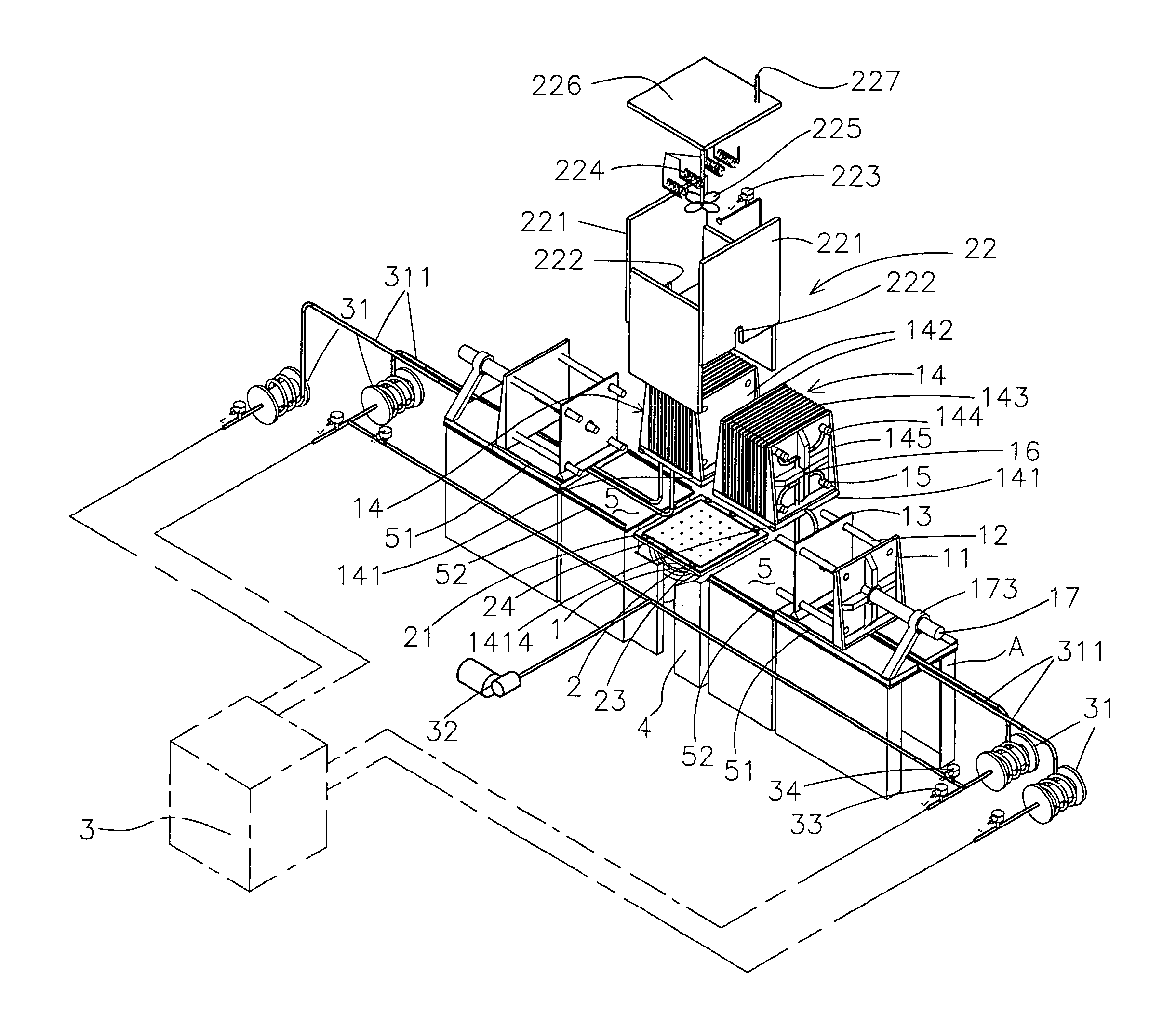
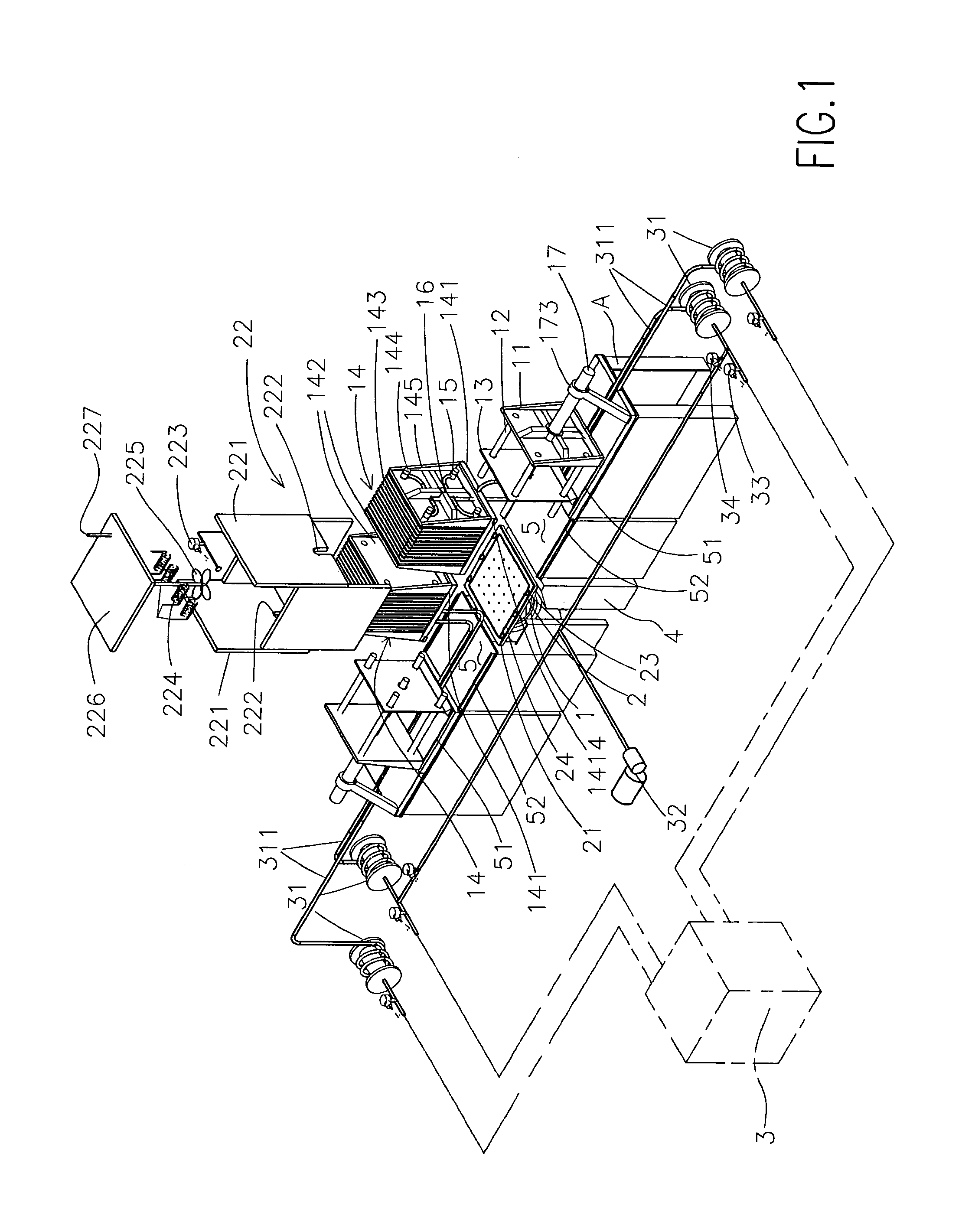
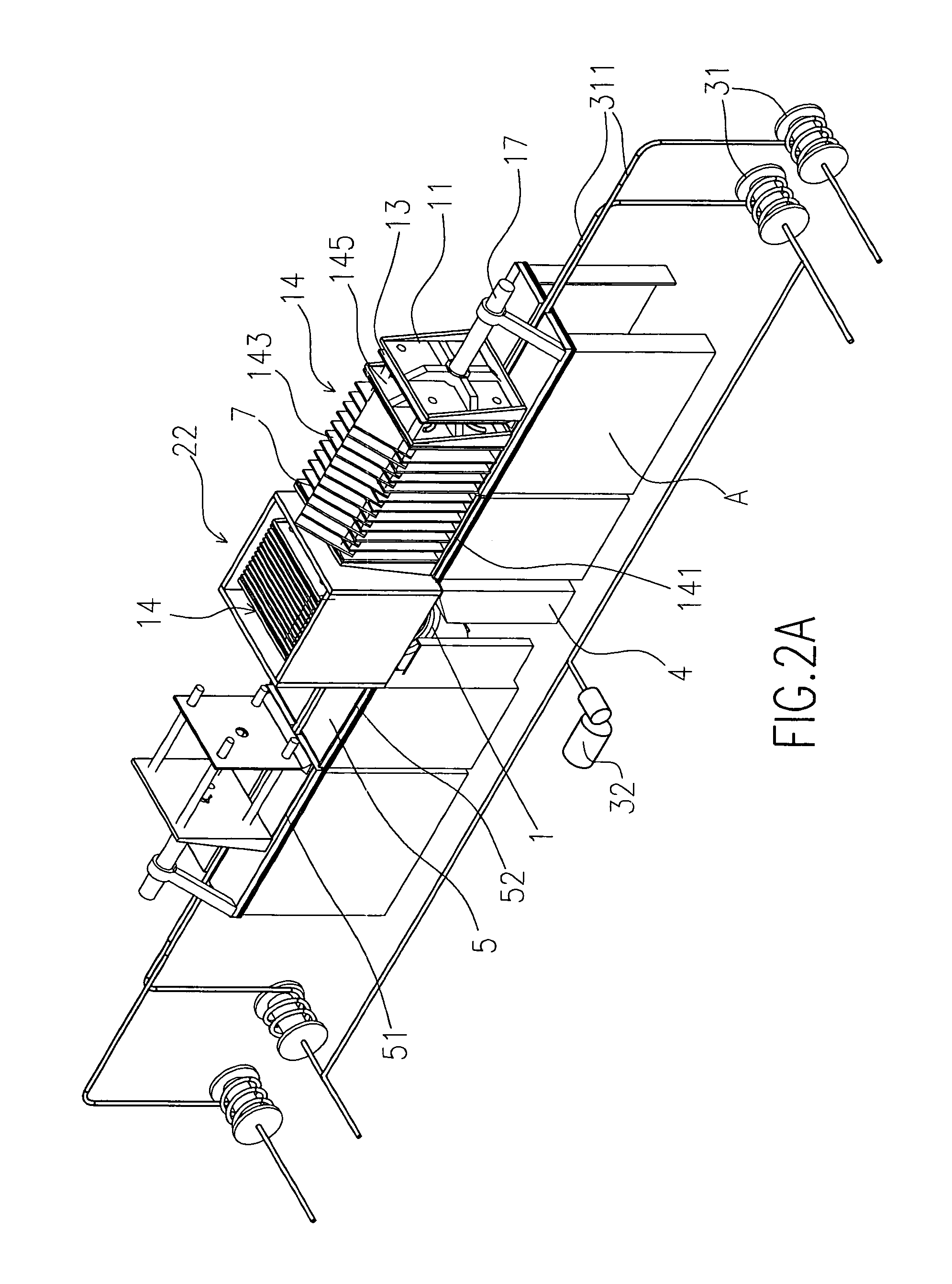
[0027]The production ESS system is shown in FIG. 1. It consists of a shaker (1), a head expander (2), a fast ramping insulated temperature chamber (22), two transporting trays (141), two PCB accordion fixture assemblies (14), a vacuum pump (32), a compressed air supply system (3) and a base table (A). Under the middle of this base table (A) is a shaker (1). On top of this shaker (1) is a head expander (2) that has an O-ring (24) on its perimeter. The design on both sides of the shaker chamber assembly is symmetrical; each side consists of an assembly table (5) and a system that will move, collapse and expand the PCB accordion fixture assembly (14). The system that will move, collapse, and expand the PCB accordion fixture assembly (14) consists of a fixed extension tubular shaft support plate (11) with the 4 extension tubular shafts (12) attached to the end support plate (11), a pneumatic cylinder (17), and a moveable end support (13). The movable extension tubular shaft support (13)...


PUM


Abstract

A production line environmental stress screening system consists of a shaker, a head expander, a fast ramping temperature chamber, two transporting trays, two PCB according fixture assemblies, a vacuum pump, a compressed air system, and a base table. The two PCB according fixture assemblies move back and forth and alternately enter the fast ramping temperature chamber to receive vibration and high and low temperature screening. This system will greatly reduce the screening time required, drastically increase the production efficiency and significantly reduce the screening cost.

Description

BACKGROUND OF THE INVENTION[0001]1. Field of the Invention[0002]The present invention relates generally to environmental testing and, more particularly, to a new methodology and production line system for Environmental Stress Screening (ESS).[0003]2. Description of the Prior Art[0004]Manufacturers have observed that devices experience a high failure rate immediately after being placed in service, often referred to as “infant mortality,” and near the end of their service life, often referred to as “old age.” During a device's “mid-life” between infant mortality and old age, failure rates usually drop precipitously to a much lower level than those experienced during infant mortality and old age. Consequently, if before shipping a product a manufacturer can reliably and economically identify and eliminate particular sub-assemblies or parts in those devices that may suffer from infant mortality, the manufacturer can significantly improve the reliability of its products, while also signi...

Claims


Application Information

Patent Timeline
Patent Type & Authority Patents(United States)
IPC IPC(8): G01R31/02
CPCG01R31/2817
Inventor LIU, HONG-SUN
Owner LIU HONG SUN
Learn More