
Device for controlling a frequency response by scaling an impedance

a frequency response and impedance scaling technology, applied in the field of signal filtering devices, can solve problems such as increased product cost, signal distortion or attenuation, and burdensomeness

Inactive Publication Date: 2006-03-21
SAMSUNG ELECTRONICS CO LTD
View PDF16 Cites 6 Cited by
  • Summary
  • Abstract
  • Description
  • Claims
  • Application Information

AI Technical Summary

Benefits of technology

This solution enables easy control of frequency response by scaling impedance, reducing chip size and parasitic capacitance, while maintaining desired signal quality and reducing harmonic generation.

Problems solved by technology

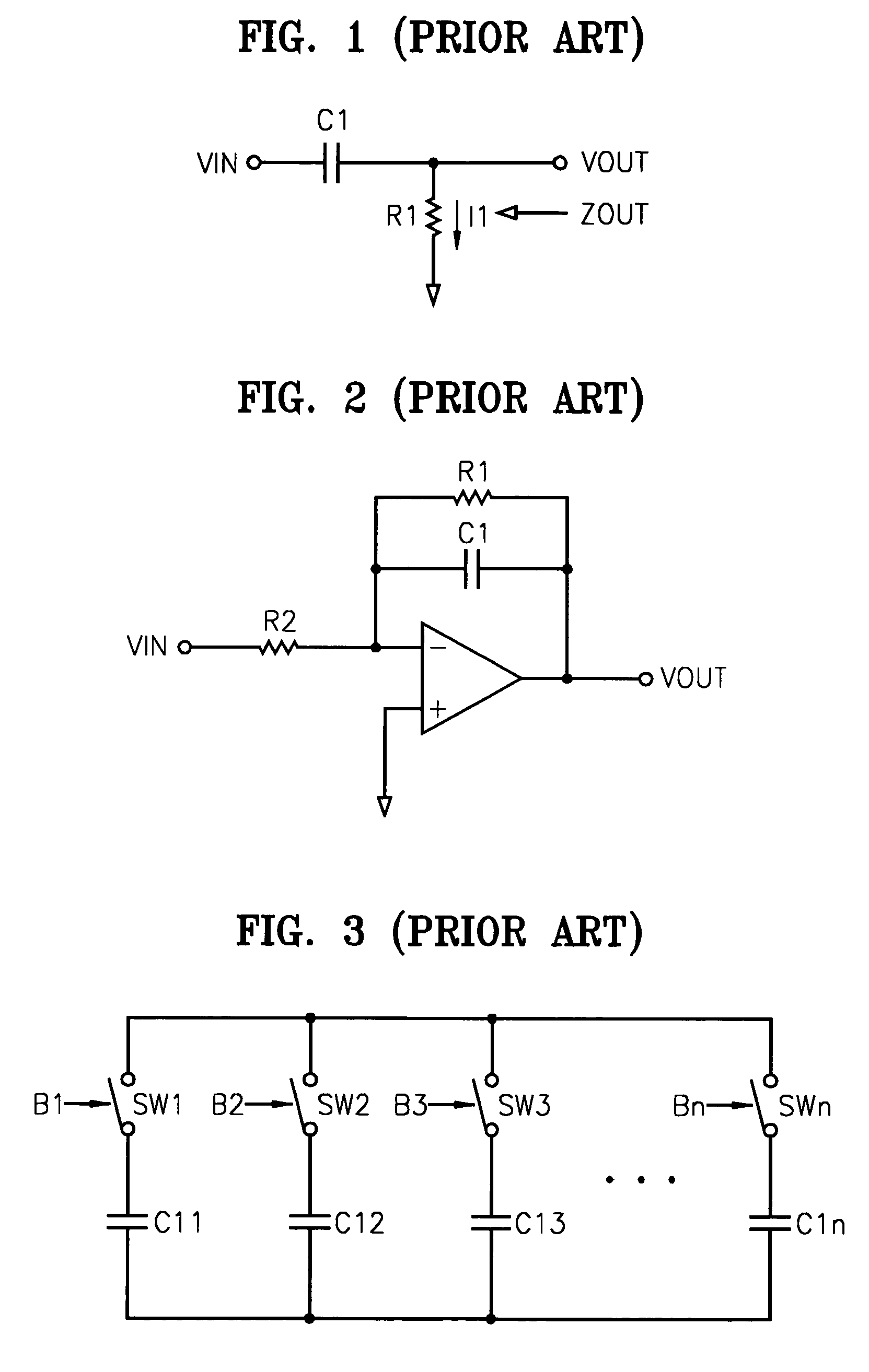
An impedance component having a high value is typically larger than an impedance component having a low value and can become burdensome to incorporate into an integrated circuit (IC).
As a result, an impedance component having a high value typically increases product cost and causes high parasitic capacitance that may result in signal distortion or attenuation.
The resulting large chip size is disadvantageous for at least two reasons: (1) integration problems resulting from its increased size; and (2) reduction in the received signal due to high parasitic capacitance at an output node of the high-pass filter.
As a result, the circuit becomes complex, and the tuning accuracy and the range of the capacitance are defined by the number of capacitors and control bits.
A common resistance and / or capacitance controlling circuit can become complex, thus making it difficult to control its frequency response.

Method used


Image

  • Device for controlling a frequency response by scaling an impedance
  • Device for controlling a frequency response by scaling an impedance
  • Device for controlling a frequency response by scaling an impedance

Examples


Embodiment Construction

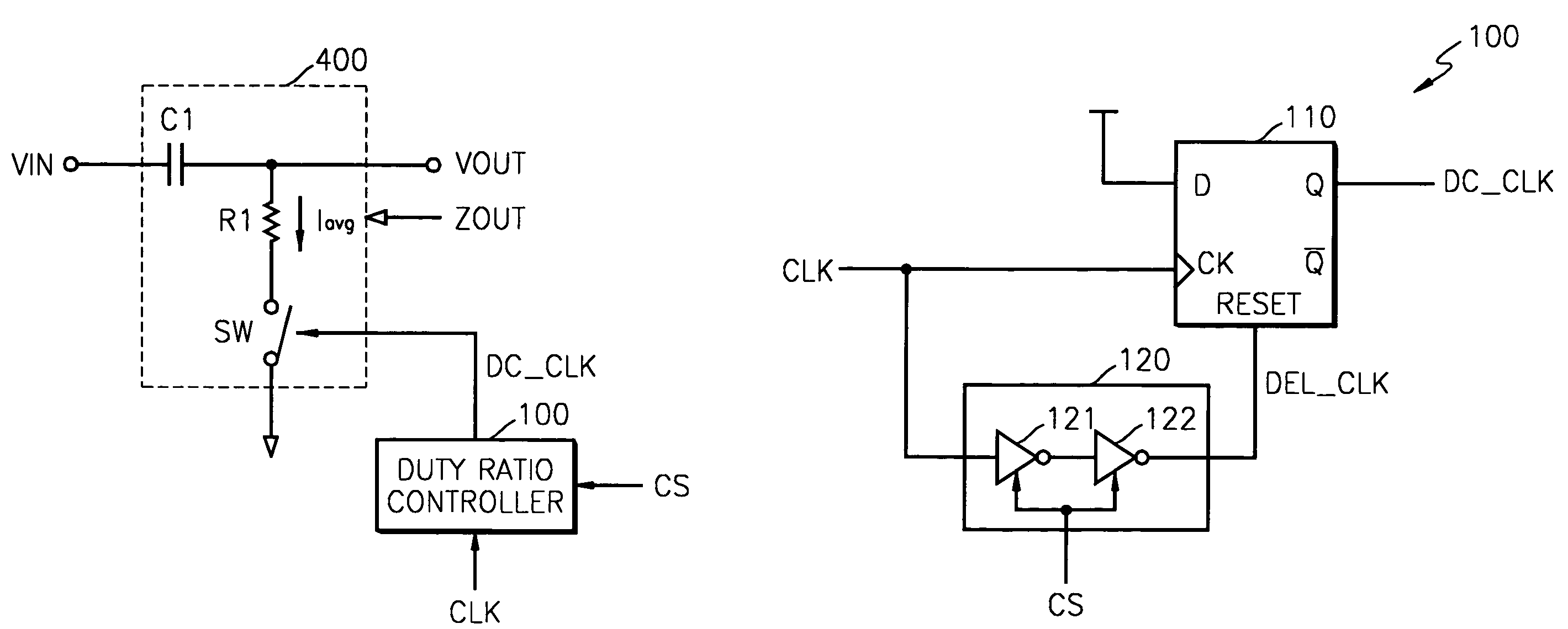
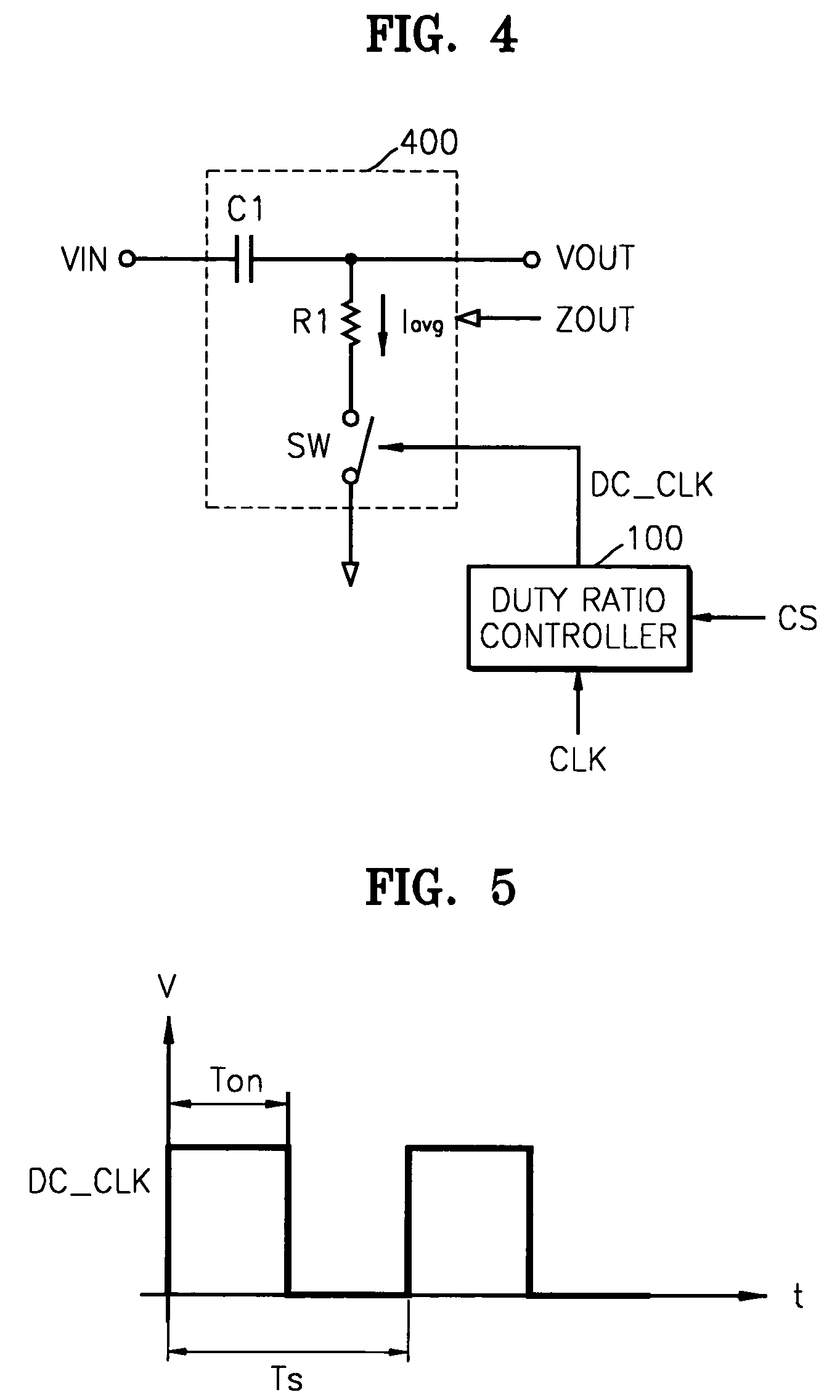
[0031]FIG. 4 illustrates a device for controlling a frequency response by scaling an impedance, according to an exemplary embodiment of the present invention. Referring to FIG. 4, the device of FIG. 4 includes a duty ratio controller 100 and a filter 400.

[0032]The duty ratio controller 100 controls the duty ratio of a clock signal CLK in response to a duty control signal CS and generates a duty-controlled clock signal DC_CLK. In this embodiment, the clock signal CLK has a duty ratio of 50%. The clock signal CLK with a duty ratio of 50% is maintained at the same ratio from a high level state to a low level state. In other words, the rate of the clock signal CLK at a high level is 50%. FIG. 5 illustrates a waveform of the duty-controlled clock signal DC_CLK. Referring to FIG. 5, the duty ratio of the duty-controlled clock signal DC_CLK is defined by Ton / Ts. In FIG. 5, when Ton is half of Ts, the duty ratio is 50%. The duty-controlled clock signal DC_CLK has a frequency that is at leas...


PUM


Abstract

Provided is a device for controlling a frequency response by scaling an impedance. The device includes a filter and a duty ratio controller. The filter generates an output signal after removing a frequency from an input signal, and comprises a first impedance component and a switch. The switch, which is serially connected to the first impedance component, is switched on or off in response to a duty-controlled clock signal. The duty ratio controller receives a clock signal, controls a duty ratio of the clock signal, and generates the duty-controlled clock signal. The duty ratio controller comprises a flip-flop, which has a clock terminal that receives the clock signal, and a reset terminal, which receives a delayed signal obtained after delaying the clock signal by a time delay. The duty ratio controller further comprises a delay component that receives the clock signal, generates the delayed signal, and controls the time delay in response to a duty control signal.

Description

BACKGROUND OF THE INVENTION[0001]1. Technical Field[0002]The present invention relates to a signal filtering device, and more particularly, to a device for controlling a frequency response using impedance scaling.[0003]2. Discussion of the Related Art[0004]In general, signal filtering devices having a particular frequency response include an impedance component such as a resistor, an inductor, or a capacitor. An impedance component having a high value is typically larger than an impedance component having a low value and can become burdensome to incorporate into an integrated circuit (IC). As a result, an impedance component having a high value typically increases product cost and causes high parasitic capacitance that may result in signal distortion or attenuation.[0005]One such example of an IC using an impedance component having a high value (e.g., a high value resistor) is a direct current (DC) offset removal circuit, which can be found in direct conversion receivers used in mob...

Claims


Application Information

Patent Timeline
Patent Type & Authority Patents(United States)
IPC IPC(8): H03B1/00H03H1/02H03H19/00
CPCH03H19/008H03H1/02
Inventor KIM, JAE-WAN
Owner SAMSUNG ELECTRONICS CO LTD
Learn More