

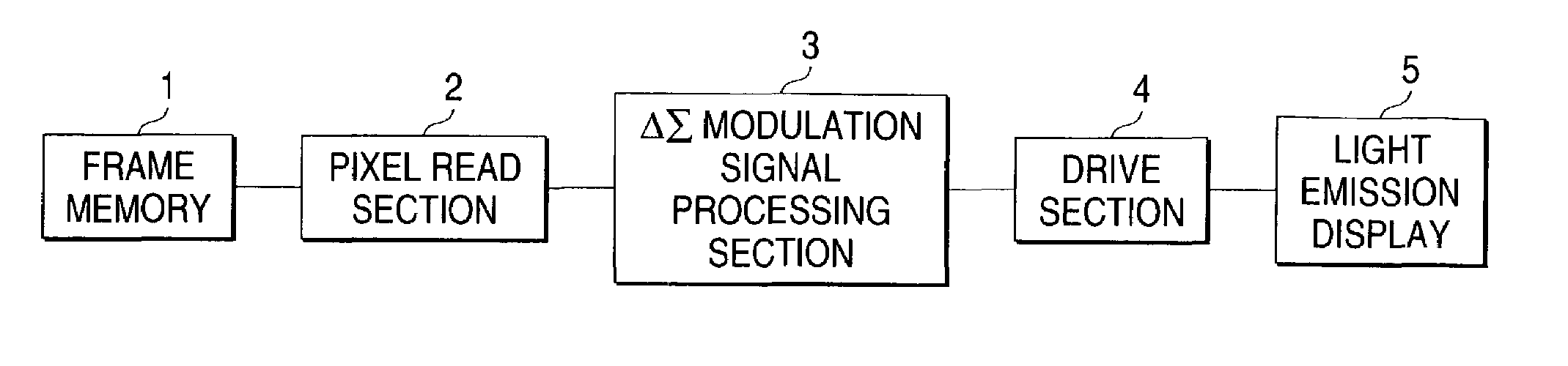
Light emission display drive method and drive apparatus using a modulator capable of performing control at three or more levels in an output brightness value
a technology of light emission display and modulator, which is applied in the direction of static indicating devices, instruments, solid-state devices, etc., can solve the problems of poor linearity and stability of gate voltage vs drain current characteristics, rapid brightness level difference in high-order bit carry, and difficult to provide good performance, etc., to achieve easy representation, reduce flicker, and increase the number of on times
- Summary
- Abstract
- Description
- Claims
- Application Information
AI Technical Summary
Benefits of technology
Problems solved by technology
Method used
Image

Examples
Embodiment Construction
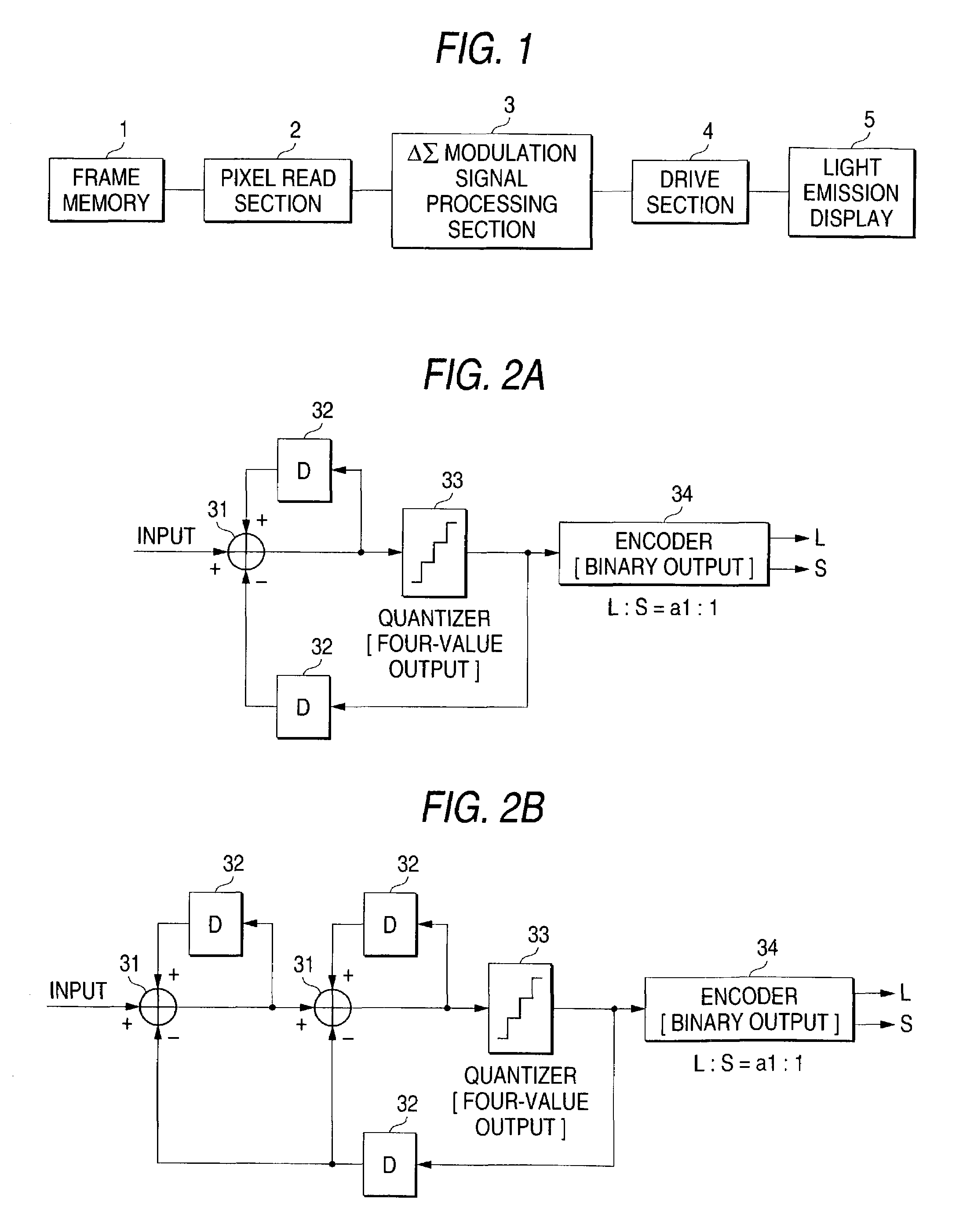
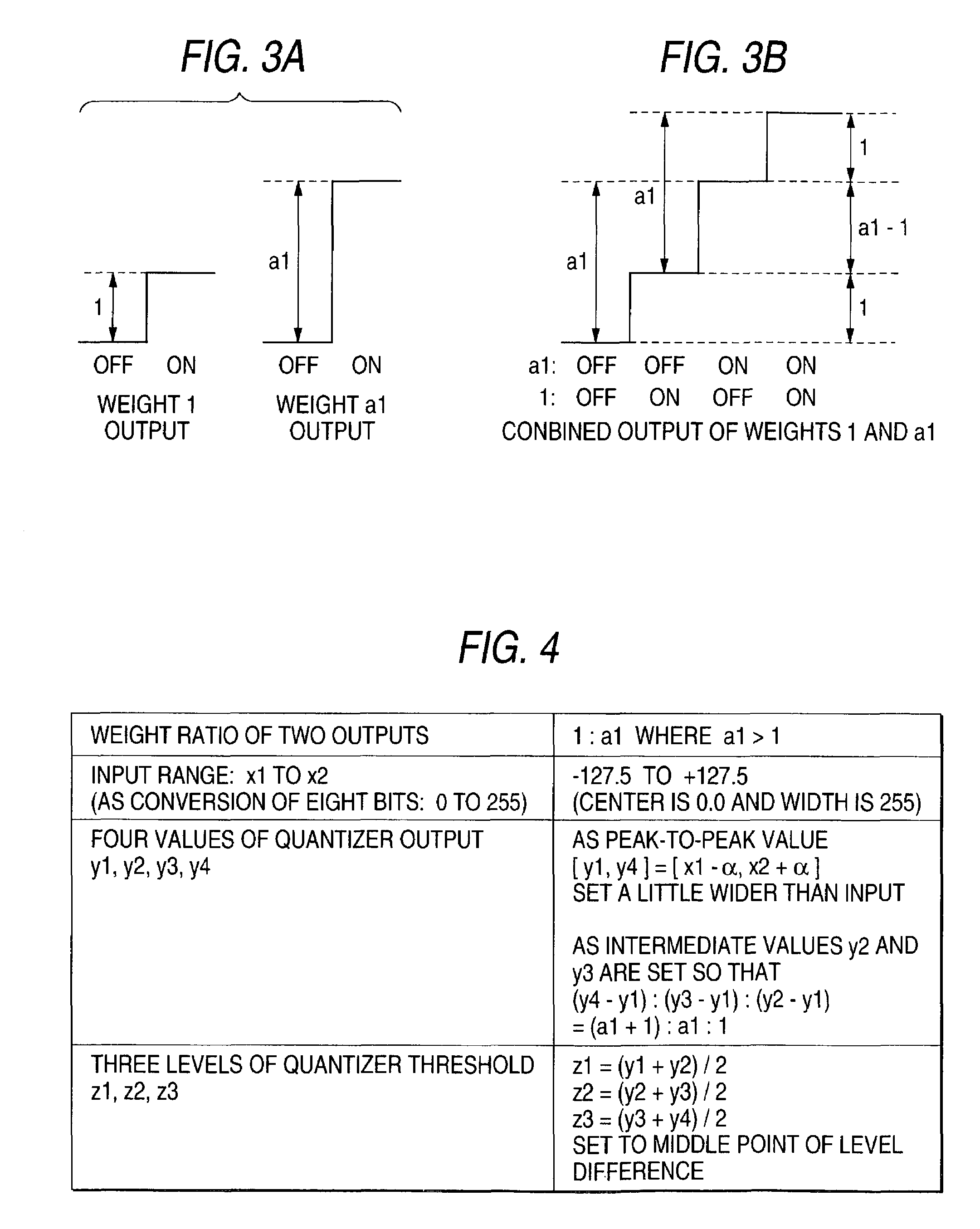
[0030]Prior to the description of embodiments of the invention, an example of the driver capable of performing control of three or more levels in the output brightness value of each light emission element described above will be discussed using a method of providing four, eight, 16 levels of output brightness value by a two-bit to four-bit weight drive method by controlling turning on and off two to four weight current sources. It is assumed that as weight examples of two-bit to four-bit outputs,
(1) for two bits, two drive sources at weight ratio a1:1 (where a1>1);
(2) for three bits, three drive sources at weight ratio a2:a1:1 (where a2>a1+1, a1>1);
(3) for four bits, four drive sources at weight ratio a3:a2:a1:1 (where a3>a2+a1+1, a2>a1+1, a1>1); and the like are provided, and they can be combined as desired for output.
[0031]It is common practice to set the weight ratio to a3:a2:a1:1=8:4:2:1, but the weight ratio is not limited to it and the fact that if any other ratio is used, the...
PUM
 Abstract
Description
Claims
Application Information