Large scale polarizer and polarizer system employing it

a polarizer and large-scale technology, applied in the field of polarizers and polarizer systems, can solve the problems of obviating the low-yield problem, reducing yield, and light scattering and random phase distortion, and simplifying the driving system of polarizers

Inactive Publication Date: 2006-03-21
LG DISPLAY CO LTD
View PDF74 Cites 48 Cited by
  • Summary
  • Abstract
  • Description
  • Claims
  • Application Information

AI Technical Summary

Benefits of technology

[0013]It is another object of the present invention to provide a polarizer system employing the large scale polarizer to simplify the process and to simplify a driving system of the polarizer.

Problems solved by technology

In the above described rubbing process, however, defects are generated by the microgrooves of the alignment layer which cause a light scattering and a random phase distortion.
Moreover, dust particles and electrostatic discharge are produced in the alignment layer, so that a thin film transistor of the substrate is damaged and the yield is decreased.
Compared with the rubbing method, there is no electrostatic discharge or dust particles, and thus the low yield problem is obviated.
In the conventional polarizer, however, because it is small, it is difficult to apply to the photo-alignment process of a large scale LCD.
And in the case of the polarizer having an absorptive mode on which polymers are deposited, the endurance and heat resistance properties are poor, the wavelength of incident light is limited.

Method used


Image

  • Large scale polarizer and polarizer system employing it
  • Large scale polarizer and polarizer system employing it
  • Large scale polarizer and polarizer system employing it

Examples


Embodiment Construction

[0031]Reference will now be made in detail to the present preferred embodiments of the invention, examples of which are illustrated in the accompanying drawings. Whenever possible, the same reference numbers will be used throughout the drawings to refer to the same or like parts.

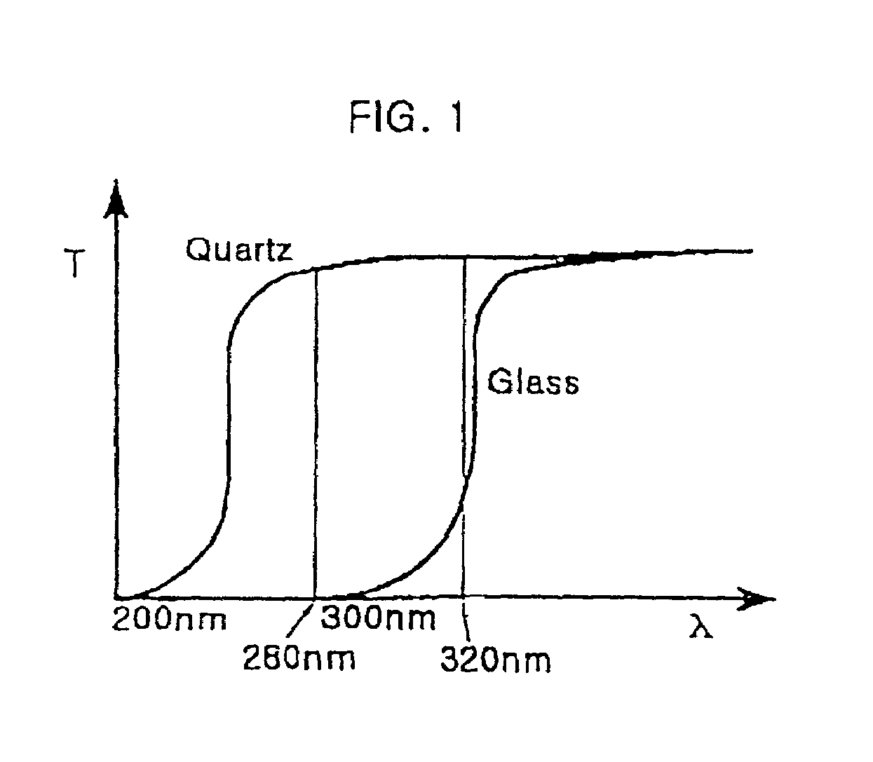
[0032]Generally, a light used in a photo-alignment process is an ultraviolet light, and more particularly a light used as a polarized light is an ultraviolet light having a wavelength approximately between 280 nm and 320 nm. FIG. 1 is a graph showing a light transmittance characteristic of quartz and glass. As shown in the figure, from the light transmittance characteristics point of view, a quartz is more preferable than a glass.

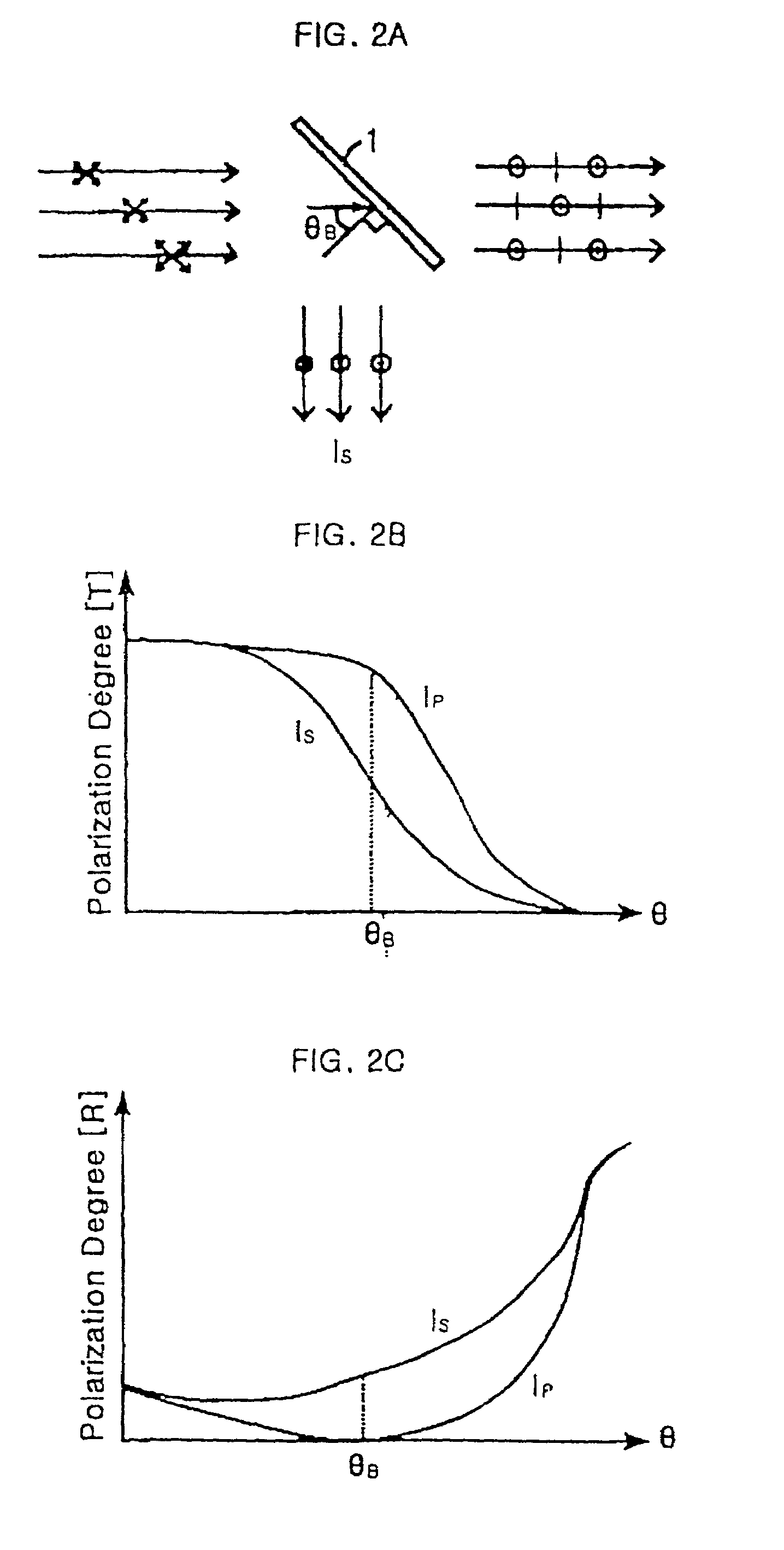
[0033]As shown in FIG. 2A, in the region irradiated by an unpolarized parallel light, a quartz substrate 1 is placed at the Brewster's θB angle with the incident light (that is, the normal of quartz substrate 1 and the incident light make the Brewster's angle θB), and the light tran...


PUM


Abstract

A large scale polarizer comprises one or more quartz substrate parts formed as a rectangle, a triangle, or a parallelogram, and a polarizer holder supporting the quartz substrate part. The polarizer holder may be in a lattice structure holding a plurality of quartz substrate parts. A polarizer system employing the large scale polarizer comprises a lens making an incident light to a parallel light, the large scale polarizer, and a moving control part coupled to and moving the large scale polarizer.

Description

[0001]This application is a divisional of application Ser. No. 09 / 618,165 filed Jul. 17, 2000, which is a continuation of application Ser. No. 09 / 084,583, filed May 27, 1998, now U.S. Pat. No. 6,292,296 which is hereby incorporated by reference for all purposes as if fully set forth herein.BACKGROUND OF THE INVENTION[0002]A. Field of the Invention[0003]The present invention relates to a polarizer and a polarizer system, and more particularly to a large scale polarizer and a polarizer system employing the large scale polarizer.[0004]B. Description of the Related Art[0005]Generally, a liquid crystal display device (LCD) comprises upper and lower substrates placed to face each other with a specific interval by a spacer, and a liquid crystal (LC) layer formed between the upper and lower substrates. The upper and lower substrates respectively have electrodes with specific patterns on their faced sides. And an alignment layer is formed over the electrodes to impart a pretilt angle on the ...

Claims


Application Information

Patent Timeline
Patent Type & Authority Patents(United States)
IPC IPC(8): G02B27/28G02B5/30
CPCG02B5/3025
Inventor CHOI, JAE BEOMSONG, BYUNG DUCKYOON, KI HYUK
Owner LG DISPLAY CO LTD
Why Eureka
Try Eureka