Method and apparatus for calibrating volumetric computed tomography systems

a computed tomography and volumetric technology, applied in the field of computed tomography systems, can solve the problems of difficult or impossible to obtain adequate image quality from a scanner, phantoms work only over a limited range, and the technique is not applicable to vct scanners

Inactive Publication Date: 2006-03-21
GE MEDICAL SYST GLOBAL TECH CO LLC
View PDF9 Cites 117 Cited by
  • Summary
  • Abstract
  • Description
  • Claims
  • Application Information

AI Technical Summary

Benefits of technology

[0012]It will thus be appreciated that configurations of the present invention allow for a relatively simple determination of various geometric parameters of a volumetric computed tomographic system that is resistant to measurement errors and phantom construction errors. Configurations of the present invention are also useful with a wide range of geometries and magnifications.

Problems solved by technology

Without these critical alignment parameters, it is difficult or impossible to obtain adequate image quality from a scanner, as the image reconstruction process requires an accurate knowledge of scanner geometry to avoid artifacts and blurring in reconstructed images.
This technique is not applicable to VCT scanners, for which a number of additional parameters are required.
However, such phantoms work only over a limited range of geometries.
In particular, the diameter of the cylinder and pitch of the helical matrix of the phantom limit the utility of such phantoms to a narrow range of magnifications and cone angles.
Also, calibration methods using such phantoms are poorly conditioned, and it is difficult to use the resulting geometry information to reliably adjust the physical characteristics of the scanner.

Method used


Image

  • Method and apparatus for calibrating volumetric computed tomography systems
  • Method and apparatus for calibrating volumetric computed tomography systems
  • Method and apparatus for calibrating volumetric computed tomography systems

Examples


Embodiment Construction

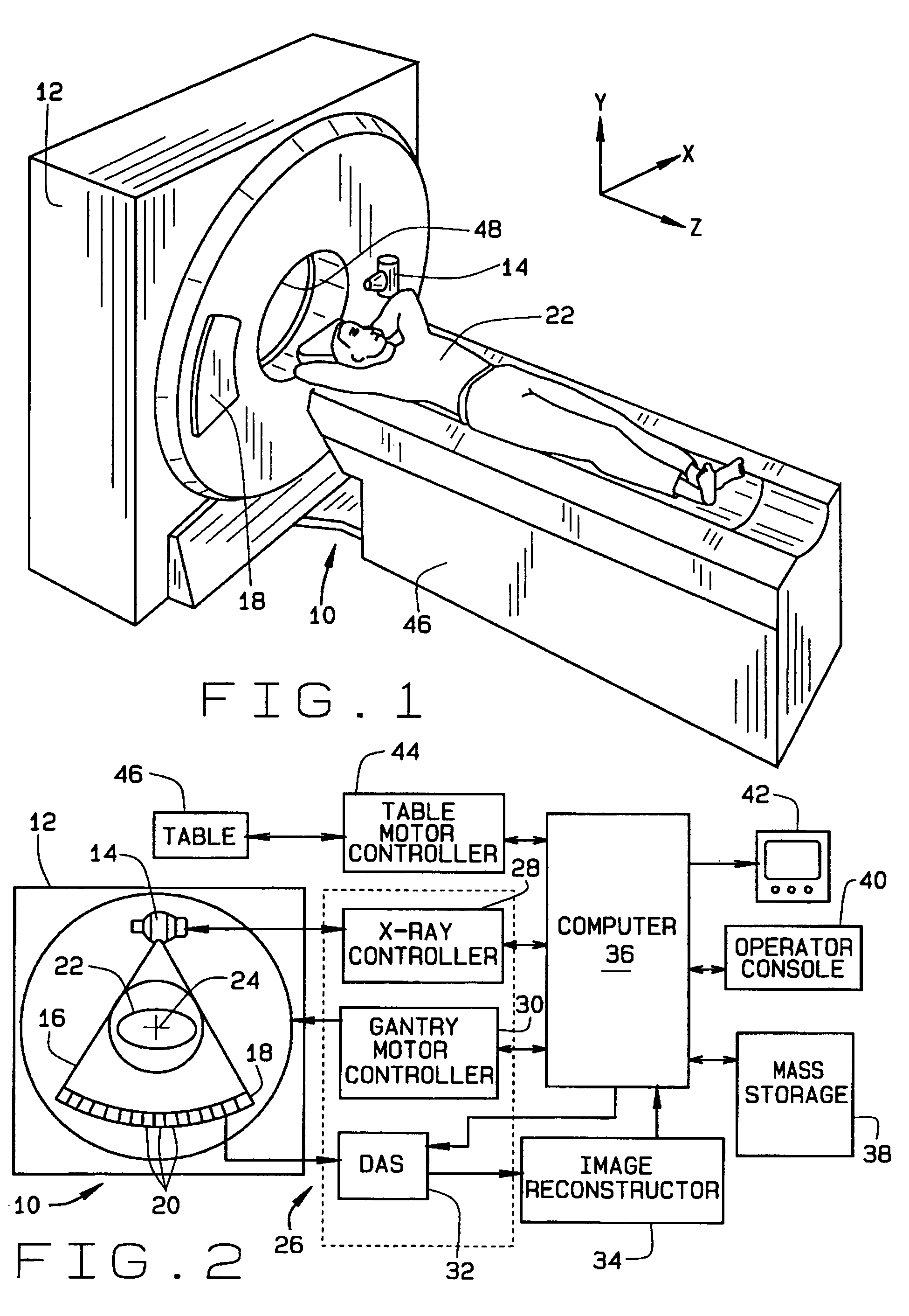
[0023]Referring to FIG. 1 and FIG. 2, a computed tomography (CT) imaging system 10 is shown as including a gantry 12 representative of a third generation CT scanner. Gantry 12 has an x-ray source 14 that projects a beam of x-rays 16 toward a detector array 18 on opposite side of gantry 12. Detector array 18 is formed by detector elements 20 which together sense the projected x-rays that pass through an object 22, for example a medical patient. Each detector element 20 produces an electrical signal that represents the intensity of an impinging x-ray beam and allows computation of the attenuation of the beam as it passes through patient 22. During a scan to acquire x-ray projection data, a rotating portion of gantry 12 and the components mounted thereon rotate about a center of rotation 24. Detector array 18 may be fabricated in a single slice, multi-slice, or area configuration. In a multi-slice or area configuration, as in various configurations of the present invention, detector ar...


PUM


Abstract

The present invention provides a method for determining a geometry of a scanning volumetric computed tomographic (CT) system having a rotation axis, a rotational plane, an x-ray source and a detector. The method includes scanning a phantom having a series of spatially separated discrete markers with the scanning volumetric computed tomographic system, wherein the markers are configured on a supporting structure of the phantom so as to permit separate identification of each marker in a collection of projection images. The method further includes locating images of the markers in each projection, using the located marker images to assign marker locations to tracks, and using the assigned tracks, determining a relative alignment between the detector, the source, and the rotation axis of the scanning volumetric computed tomographic system.

Description

STATEMENT REGARDING FEDERALLY SPONSORED RESEARCH & DEVELOPMENT[0001]The U.S. Government has a paid-up license in this invention and the right in limited circumstances to require the patent owner to license others on reasonable terms as provided by the terms of contract no. DAMD 170220004 awarded by the Department of Defense.BACKGROUND OF THE INVENTION[0002]This invention relates generally to computed tomographic systems and more particularly to methods and apparatus for determining geometric parameters from volumetric computed tomography (CT) systems.[0003]In at least one known computed tomography (CT) imaging system configuration, an x-ray source projects a fan-shaped beam which is collimated to lie within an X-Y plane of a Cartesian coordinate system and generally referred to as the “imaging plane”. The x-ray beam passes through the object being imaged, such as a patient. The beam, after being attenuated by the object impinges upon an array of radiation detectors. The intensity of...

Claims


Application Information

Patent Timeline
Patent Type & Authority Patents(United States)
IPC IPC(8): A61B6/03A61B6/00
CPCA61B6/583A61B6/032
Inventor BASU, SAMIT KUMAREDIC, PETER MICHAELDE MAN, BRUNO KRISTIAAN BERNARD
Owner GE MEDICAL SYST GLOBAL TECH CO LLC
Why Eureka
Try Eureka