Optical network units preconfigured to accept predetermined subsets of wavelengths

a technology of optical network units and wavelengths, applied in the field of optical network units, can solve the problems of increasing delay on that channel, unable to redistribute bandwidth in response, and simple implementation,

Inactive Publication Date: 2006-03-21
FUJITSU LTD
View PDF11 Cites 58 Cited by
  • Summary
  • Abstract
  • Description
  • Claims
  • Application Information

AI Technical Summary

Benefits of technology

[0019]According to an embodiment of a first aspect of the present invention there is provided an optical network comprising: a plurality of optical network units; and optical source means connected and arranged to transmit light signals to each of said plurality of optical network units; wherein the said optical source means are capable of transmitting light signals at one or more of a plurality of different wavelengths, at least one optical network unit being operable to accept more than one of the said wavelengths, and each wavelength of the said plurality being accepted by at least one of the said optical network units such that each such wavelength is accepted by a different subset of optical network units, the optical network further comprising control means operable to cause the said optical source means to transmit light signals at one or more selected such wavelengths corresponding to respective desired subsets of the said optical network units.
[0020]According to an embodiment of a second aspect of the present invention there is provided control circuitry for use in an optical network, which network comprises a plurality of optical network units and optical source means connected and arranged to transmit light signals to each of said plurality of optical network units, said optical source means being capable of transmitting light signals at one or more of a plurality of different wavelengths, at least one optical network unit being operable to accept more than one of the said wavelengths, and each wavelength of the said plurality being accepted by at least one of the said optical network units such that each such wavelength is accepted by a different subset of optical network units, the control circuitry being operable to cause the said optical source means to transmit light signals at one or more selected such wavelengths corresponding to respective desired subsets of the said optical network units.
[0021]According to an embodiment of a third aspect of the present invention there is provided a dynamic bandwidth assignment method for an optical network comprising optical source means capable of transmitting light signals at one or more of a plurality of different wavelengths, each of the said wavelengths being accepted by a different subset of optical network units of the said network, in which method: light signals are transmitted by the said optical source means at one or more wavelengths, selected from the said plurality of wavelengths, corresponding to one or more desired subsets of optical network units, and, in response to a required bandwidth redistribution, the said one or more wavelengths at which light signals are transmitted by the said optical source means are changed to one or more different wavelengths, selected from the said plurality, which correspond to one or more different desired subsets of optical network units.

Problems solved by technology

This type of scheme is simple to implement but does not allow the redistribution of bandwidth in response to fluctuations in demand.
There is, however, a major drawback with this approach to dynamic assignment of wavelengths, which is that the information about current bandwidth requirements is held at the central office 1, and is separated from the location of the tunable components in the ONUs 9.
As retuning is normally done in response to the overloading of a wavelength channel, this lag causes a build up of traffic and consequent increase in delay on that channel.
Thirdly, the system would be more robust; if the tuning is at the ONU 9 then either an acknowledgement of successful retuning is required, resulting in further delay, or there is the risk of an error in retuning resulting in the loss of cells transmitted to the ONU 9 on the new wavelength.
Fourthly, the more expensive, tunable components would be placed at the head end, where only a few are required, rather than providing expensive tunable systems at each ONU; this would lead to a cost reduction.
There are still certain drawbacks, however, to such a fixed-filter, tunable-laser approach.
This means that bandwidth would be wasted when the network transmits broadcast or multicast traffic, because the cell needs to be replicated and retransmitted on the wavelength of each destination ONU 9.
Secondly, constant retuning of the lasers at the head end would be required.
Consequently, if the tuning time is non-negligible, then a loss of bandwidth would result.

Method used


Image

  • Optical network units preconfigured to accept predetermined subsets of wavelengths
  • Optical network units preconfigured to accept predetermined subsets of wavelengths
  • Optical network units preconfigured to accept predetermined subsets of wavelengths

Examples


Embodiment Construction

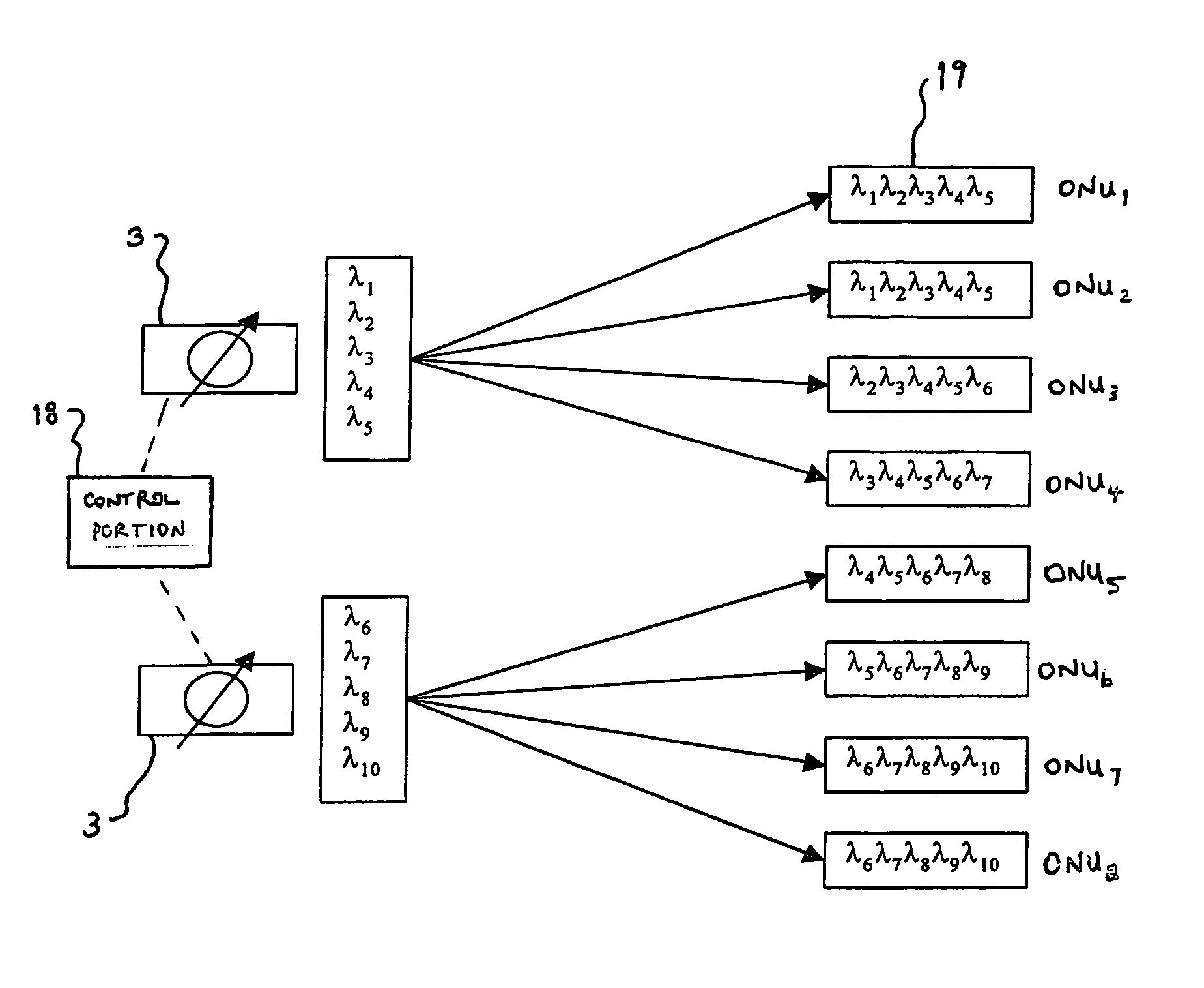
[0050]FIG. 3 shows the basic principle of a staggered filter optical network architecture embodying the present invention. In this embodiment, there are two tunable lasers 3 capable of transmitting a total of 10 wavelengths λ1 to λ10 to a total of eight optical network units 19, ONU1 to ONU8. The first tunable laser 3 is capable of transmitting one of five wavelengths λ1 to λ5, and in the present example is tuned to λ3. The second tunable laser is capable of transmitting one of five wavelengths λ6 to λ10, and in the present example is tuned to λ8. Control portion 18 is in communication with, and controls the operation of, the tunable lasers 3.

[0051]Each optical network unit 19 employs a bandpass filter which allows a group of five consecutive transmitted wavelengths to be passed. For example, as indicated in FIG. 3, ONU1 passes wavelengths λ1 to λ5, while ONU4 passes wavelengths λ3 to λ7. The table of FIG. 4 summarises the passband of the filters in each of the ONUs 19, where shaded...


PUM


Abstract

An optical network is provided which comprises a plurality of optical network units (19) and optical source means (3) connected and arranged to transmit light signals to each of the plurality of optical network units (19). The optical source means (3) are capable of transmitting light signals at one or more of a plurality of different wavelengths and at least one optical network unit (19) is operable to accept more than one of the said wavelengths. Further, each wavelength of the plurality is accepted by at least one of the optical network units (19) such that each such wavelength is accepted by a different subset of optical network units (19). The optical network further comprises control means (18) operable to cause the optical source means (3) to transmit light signals at one or more selected such wavelengths corresponding to respective desired subsets of the optical network units (19).

Description

BACKGROUND OF THE INVENTION[0001]1. Field of the Invention[0002]This invention relates to optical networks.[0003]2. Description of the Related Art[0004]FIG. 1A of the accompanying drawings shows in block diagram form the basic components of a passive optical network (PON). A multiwavelength optical source 3, located in a central office 1, transmits light signals consisting of multiple discrete wavelengths λ1 . . . λN down an optical fibre 10 to a wavelength division multiplexer (WDM) 7, located in a remote node 5, which then distributes the signals to a set of optical network units (ONUs) 9, via separate fibres 11. The network is described as passive since the optical routing components (such as the WDM 7) cannot actively be controlled or tuned during their operational use.[0005]The wavelength division multiplexer 7 may be one of a variety of types. An example of a simple multiplexer is a power-splitting star coupler which simply splits incoming light into all ports equally; it is t...

Claims


Application Information

Patent Timeline
Patent Type & Authority Patents(United States)
IPC IPC(8): H04J14/00H04B10/27H04B10/272H04B10/275H04B10/278H04J14/02H04L12/44
CPCH04J14/0204H04J14/0205H04J14/0213H04J14/0226H04J14/028H04J14/0246H04J14/0283H04Q11/0067H04J14/0232H04J14/0238H04J14/0282H04J14/021H04Q2011/0064
Inventor BALL, PETER RAYMONDWRIGHT, IAN ROBERTHANDLEY, MICHAEL ROBERT
Owner FUJITSU LTD
Why Eureka
Try Eureka