Man-machine interface

a man-machine interface and interface technology, applied in the field of man-machine interfaces, can solve the problems of increased manufacturing costs, health risks, damage to the potentiometer and the associated electronics, etc., and achieve the effects of reducing the amount of control a user can exercise over the device, reducing the cost, and improving the user's control

Inactive Publication Date: 2006-03-21
SCI GENERICS LTD
View PDF55 Cites 39 Cited by
  • Summary
  • Abstract
  • Description
  • Claims
  • Application Information

AI Technical Summary

Benefits of technology

[0022]One advantage of the present invention is that it enables an inexpensive, simple, robust, easily fitted fascia plate to be used to provide all (or at least a large number of) the user-visible aspects of a man-machine interface. For many domestic appliances (such as washing machines), the internal operating elements of a number of different models are very similar, if not identical, and the main distinguishing features between different devices are the user-visible aspect of the man-machine interface. Therefore, by providing the user-visible aspects of the man-machine interface on a separate, essentially modular, component which may be fitted to the rest of the device at a very late stage in the manufacture of the device (even, for example, at a retail outlet), a manufacturer is able to produce a much wider range of “different” models at a much lower cost than that at which it is currently possibly to produce just a small range of “different” models, where each different model must be modified slightly to accommodate the different man-machine interfaces.
[0023]In many cases, a very simple, intuitive, robust fascia plate may be provided which satisfies all of the functionality required of the device to which it is fitted. Such an example is described in the third embodiment. Alternatively, the amount of control which a user can exercise over a device may be increased greatly by providing a number of different overlays, each of which may be designed to provide a convenient and intuitive means for allowing the user to input controlling information to the device (in effect taking advantage of the simplicity with which multiple man-machine interfaces may be applied to a device if remotely sensed user actuable elements are employed). The first embodiment described below is an example of such an application.

Problems solved by technology

There are a number of problems with such an interface.
It is very difficult to seal around such a shaft and so there is usually a risk of contaminants such as water, soap, dirt, etc. gaining access to, and therefore possibly damaging, the potentiometer and the associated electronics.
Also, in the case of kitchen equipment, there may be health risks caused by the entrapment of fat or food particles around the shaft.
This means that if a manufacturer wishes to produce a similar appliance but with a different arrangement of switches and knobs etc, a new box with different preformed holes must be manufactured, leading to increased manufacturing costs.

Method used


Image

  • Man-machine interface
  • Man-machine interface
  • Man-machine interface

Examples


first embodiment

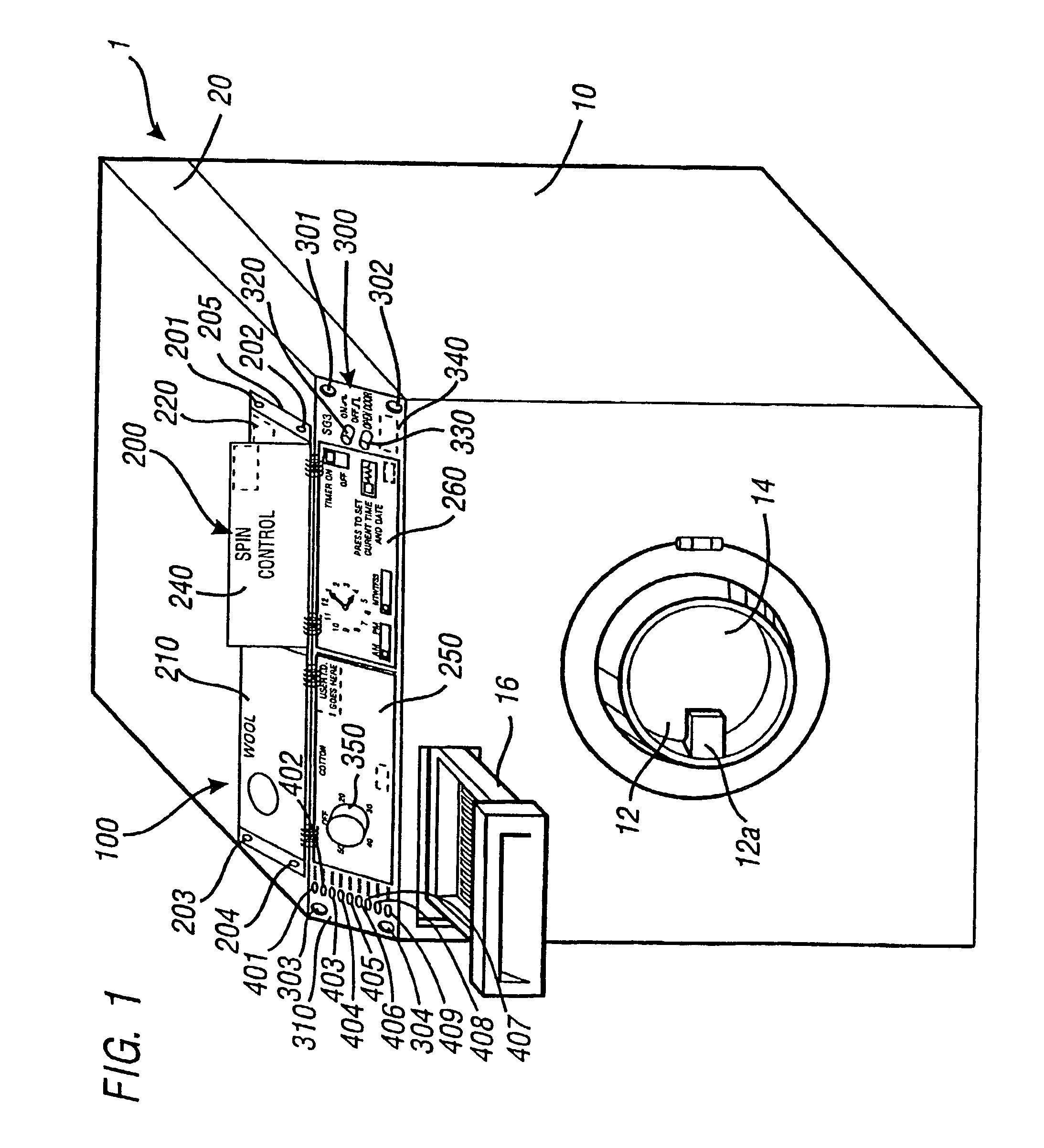
[0056]FIG. 1 shows a washing machine 1 having a main body 10 which houses a drum 14 into which dirty clothes to be washed may be placed. The main body 10 also includes a drum door 12 having a handle 12a, which opens into the drum 14 and a soap drawer 16. The washing machine 1 also includes a sealed box 20 which is fitted on top of the main body 10. In the present embodiment, the sealed box 20 houses the majority of the control circuitry for the washing machine 1 and also has a man-machine interface generally designated by the reference number 100 mounted on the front surface and the top surface of the sealed box 20 just behind the front surface.

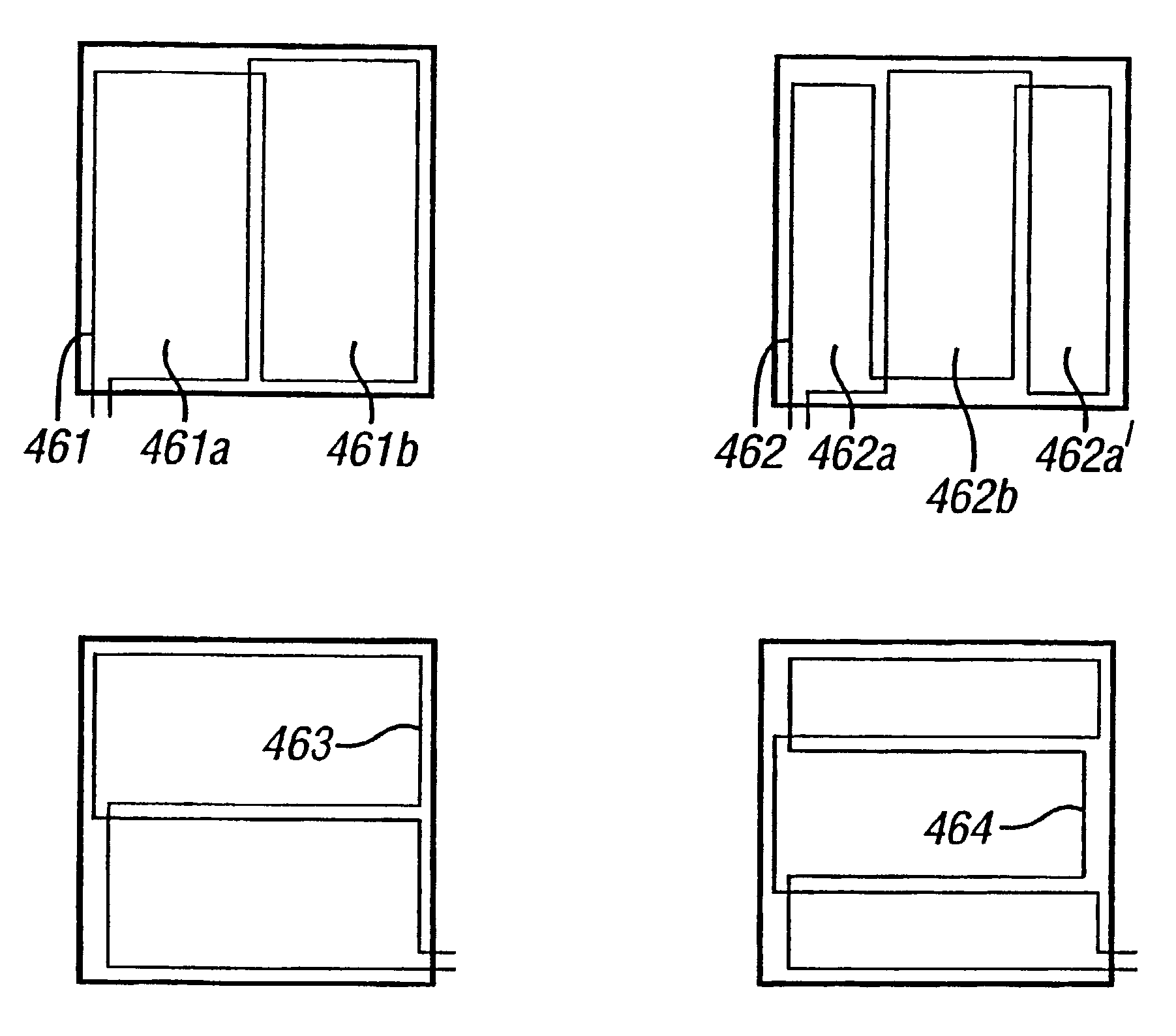
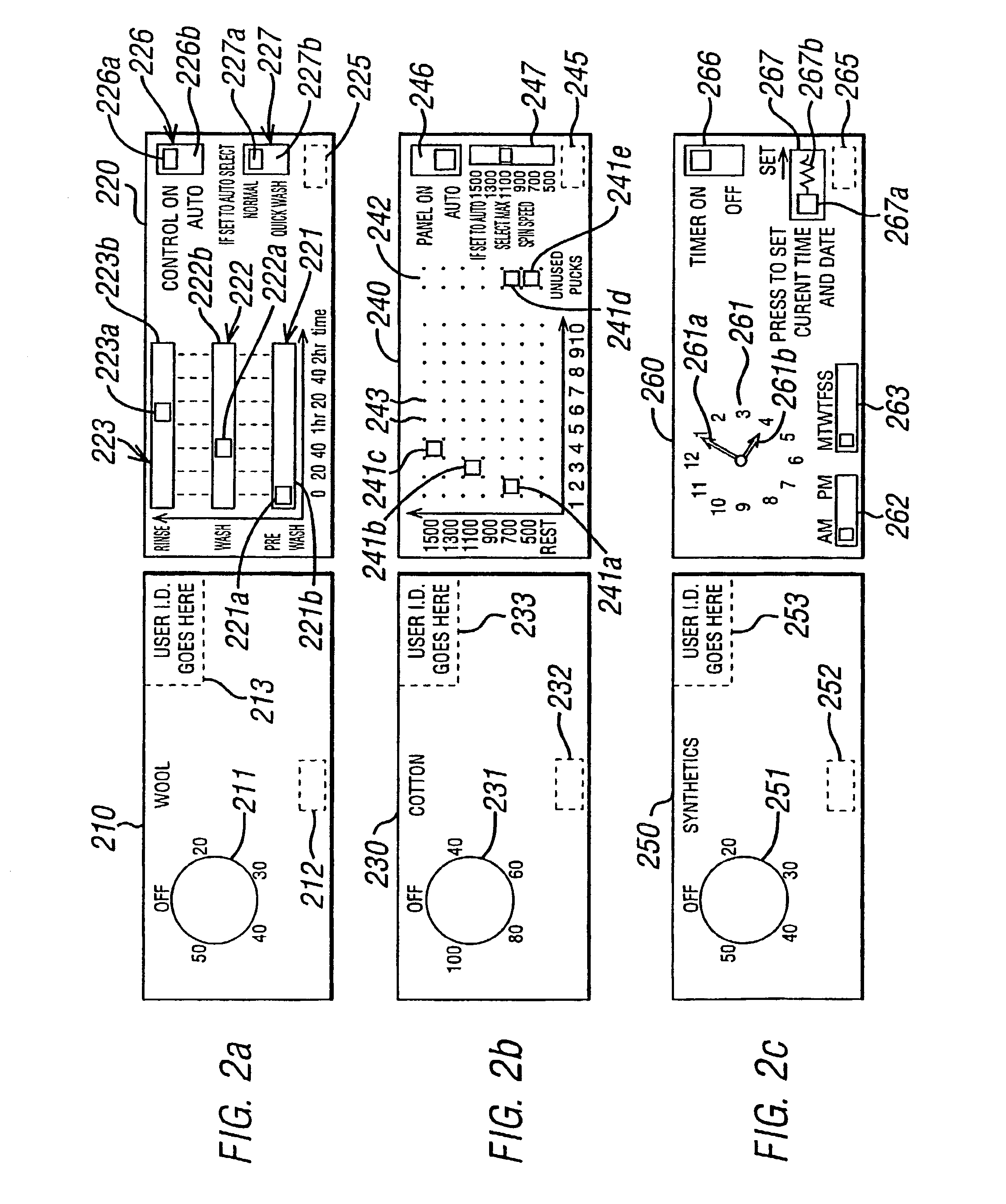
[0057]The Man-Machine Interface (MMI) 100 includes a book 200 of six loose-leaf ring-bound graphical interface panels 210, 220, 230, 240, 250, 260 three of which are left panels 210, 230, 250 and three of which are right panels 220, 240260 and which are mounted on a backing plate 205. The backing plate 205 is removably affixed to the top of t...

second embodiment

[0129]The above described first embodiment may be modified to include functionality for permitting radio frequency identification (RFID) transponders to communicate data to the washing machine 1. Such transponders may then be fitted to newly purchased garments with information which can be used to determine which master washing programme should be selected and also to set the various variable parameters within the master washing programme to customise the washing programme exactly for the garment. The user may then pass the transponder within sensing range of the facia plate 300 and the MMI 100 (which continually monitors for an RFID transponder within range) will initiate the RFID transponder into transmitting its stored data which the MMI 100 will receive and use to configure the washing programme accordingly.

[0130]FIG. 11a is a schematic block diagram of a modified analogue signal processing for inductive coils including RFID functionality block 1100 which replaces analogue signa...

third embodiment

[0135]FIG. 12a is a schematic plan view of a stove 1200 which has a fascia plate 1230 removably affixed thereto. The fascia plate 1230 includes fascia plate identifying pucks 1231, 1232, 1233 each of which includes a resonant circuit having a specified resonant frequency such that the combination of pucks 1231, 1232, 1233 and their relative positions are used to identify the fascia plate 1230 attached to the stove 1200. Removably mounted on the fascia plate 1230 are four gas control buttons 1221 to 1224 which are used both to generate a spark to ignite a corresponding gas ring 1251 to 1254 and to control the amount of gas emitted from each of the rings 1251 to 1254 (so as to control the heat generated by each of the gas rings 1251 to 1254).

[0136]FIG. 12b is an expanded plan view of the first button 1221. As shown, it comprises an outer ring 1261 for controlling the amount of gas flowing from the corresponding gas ring 1251 and an inner button 1262 which causes a spark at gas ring 12...


PUM


Abstract

A man-machine interface is provided for a domestic appliance in which remotely sensed buttons, slider bars, marker pucks and a knob are used. The sensing coils for remotely sensing the positions of the buttons, slider bars, marker pucks and the knob are formed on a printed circuit board which is located behind a sealed surface such that there is no risk of contaminants accessing the printed circuit board.

Description

CROSS REFERENCE TO RELATED APPLICATIONS[0001]This patent application claims the benefit of priority under 35 U.S.C. Section 119, to the following applications:[0002]Application Number Filed[0003]9929386.2 Dec. 10, 1999[0004]0004987.4 Mar. 1, 2000[0005]0006130.9 Mar. 14, 2000[0006]0009142.1 Apr. 13, 2000[0007]0014889.0 Jun. 16, 2000[0008]0017888.9 Jul. 20, 2000[0009]0019624.6 Aug. 9, 2000[0010]0023806.3 Sep. 28, 2000[0011]This patent application is a continuation of and claims the benefit of priority, under 35 U.S.C. Section 120 or 365(c), to application number: PCT / GB00 / 04749, filed on Dec. 8, 2000.FIELD OF THE INVENTION[0012]The present invention relates to a man-machine interface, and in particular to a man-machine interface for domestic appliances requiring an inexpensive yet reasonably sophisticated interface.BACKGROUND OF THE INVENTION[0013]White goods appliances typically include a low cost interface including one or more mechanical buttons or switches which physically make or...

Claims


Application Information

Patent Timeline
Patent Type & Authority Patents(United States)
IPC IPC(8): G05B15/00G05B11/01G05B19/042G05B19/05G06F19/00
CPCG05B19/0425G05B2219/25356G05B2219/23379G05B2219/23067
Inventor HOWARD, MARK A.DOYLE, RICHARD A.RICHARD, ALICE
Owner SCI GENERICS LTD
Why Eureka
Try Eureka