
Voice code conversion apparatus

a voice code and code technology, applied in the field of voice code conversion apparatus, can solve the problems of delay in processing, marked decline in the and inferior sound quality of reproduced voice to that of the sour

Inactive Publication Date: 2006-03-21
FUJITSU LTD
View PDF15 Cites 61 Cited by
  • Summary
  • Abstract
  • Description
  • Claims
  • Application Information

AI Technical Summary

Benefits of technology

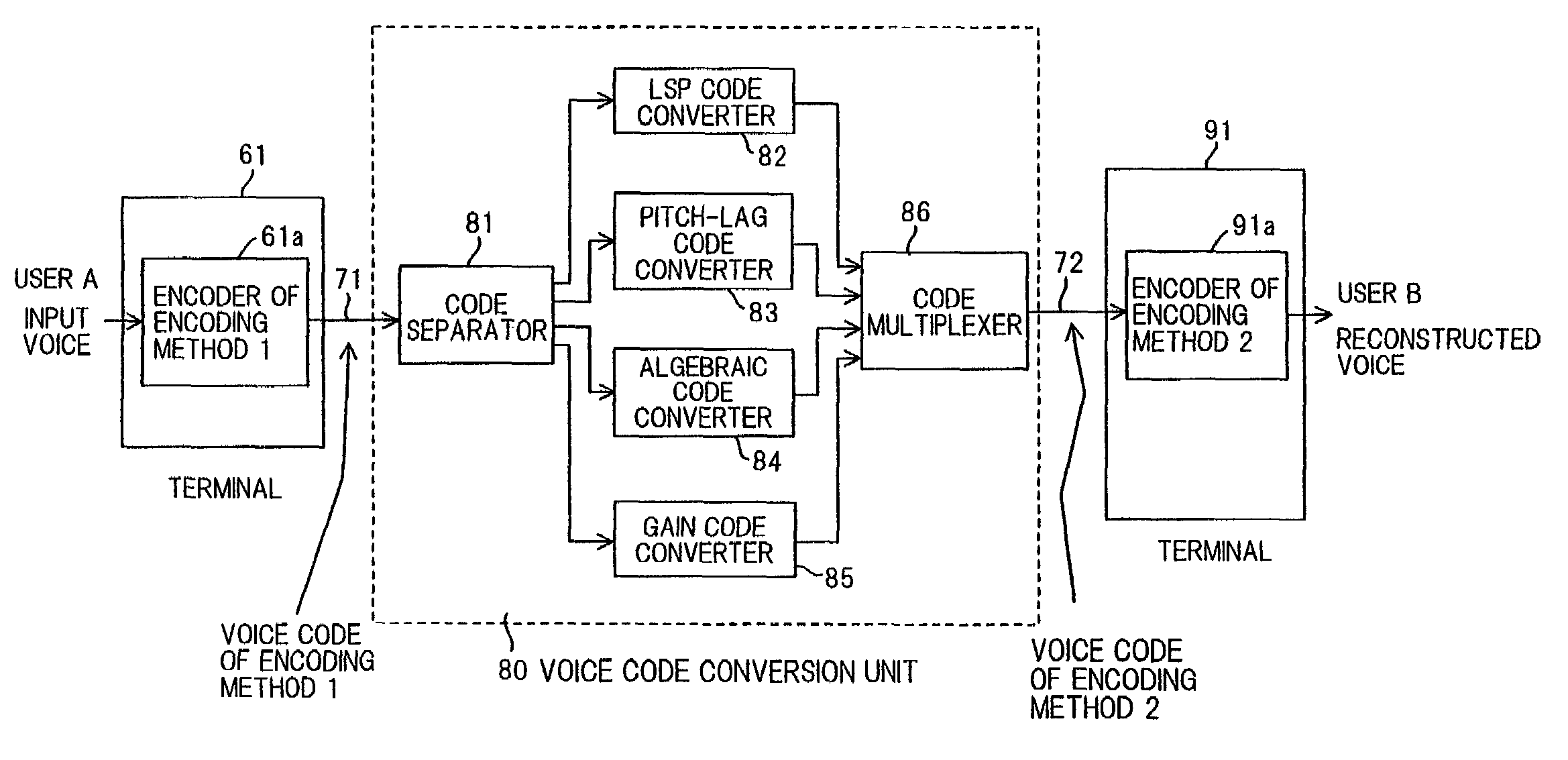
[0044]Accordingly, an object of the present invention is to so arrange it that the quality of reconstructed voice will not be degraded even when a voice code is converted from that of a first voice encoding method to that of a second voice encoding method.
[0045]Another object of the present invention is to so arrange it that a voice delay can be reduced to improve the quality of a telephone conversation even when a voice code is converted from that of a first voice encoding method to that of a second voice encoding method.
[0046]Another object of the present invention is to reduce a decline in the sound quality of reconstructed voice ascribable to transmission-path error by eliminating, to the maximum degree possible, the effects of error from a voice code that has been distorted by transmission-path error and applying a voice-code conversion to the voice code in which the effects of error have been reduced.
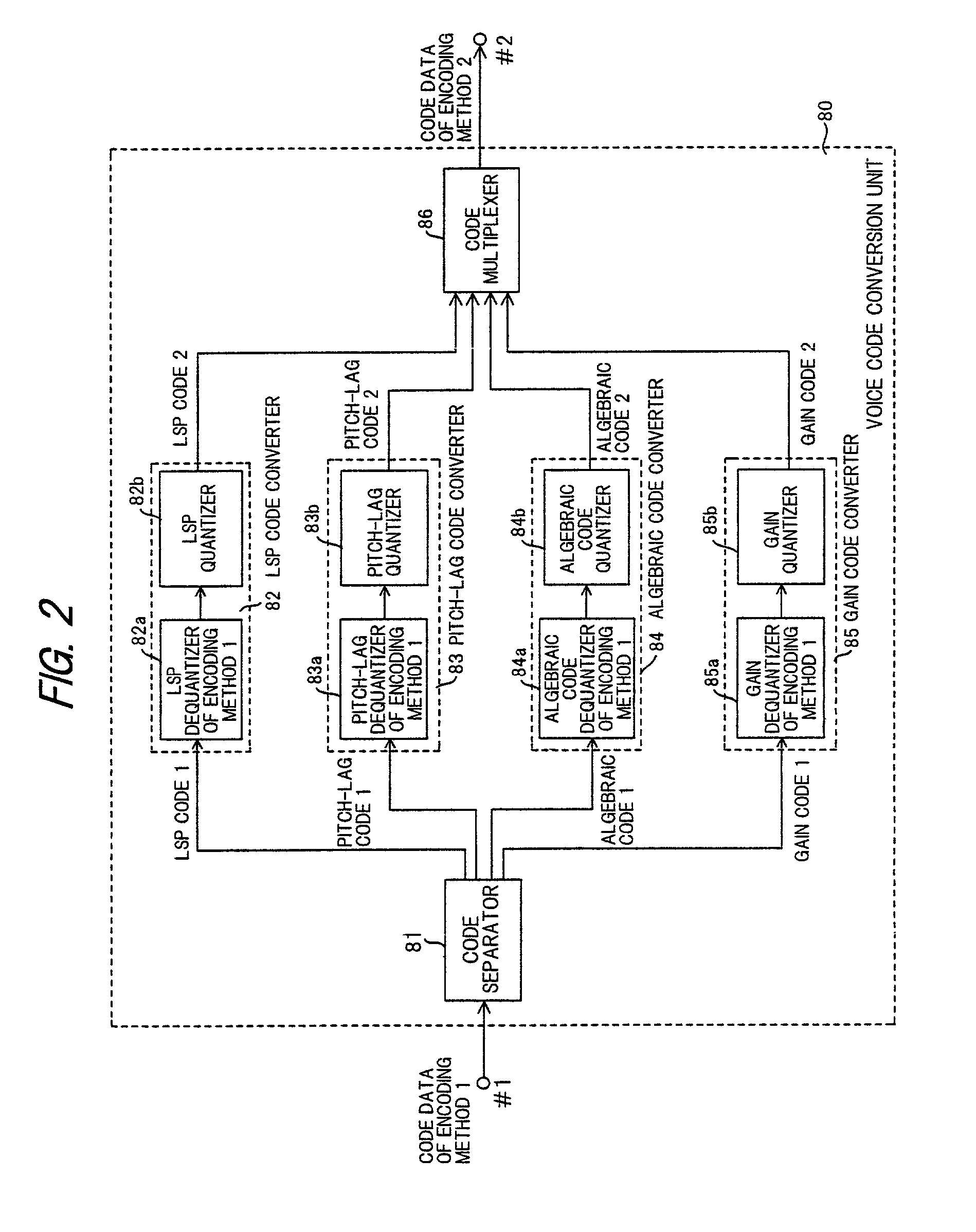
[0048]In accordance with the voice code conversion apparatus according to the present invention, a voice code based upon a first voice encoding method is dequantized and the dequantized values are quantized and encoded by a second voice encoding method. As a consequence, there is no need to output reconstructed voice in the voice code conversion process. This means that it is possible to suppress a decline in the quality of voice that is eventually reproduced and to reduce signal delay by shortening processing time.

Problems solved by technology

Voice (reproduced voice) consisting of information compressed by encoding processing contains a lesser amount of voice information in comparison with the original voice (source) and, hence, the sound quality of reproduced voice is inferior to that of the source.
When a tandem connection in which encoding and decoding are repeated is employed, a problem which arises is a marked decline in the quality of reproduced voice.
An additional problem with tandem processing is delay.
It is known that when a delay in excess of 100 ms occurs in two-way communication such as a telephone conversation, the delay is perceived by the communicating parties and is a hindrance to conversation.
It is known also that even if real-time processing can be executed in voice encoding in which frame processing is carried out, a delay which is four times the frame length basically is unavoidable.
Such a delay is perceivable by the parties in a telephone conversation and is an impediment to conversation.
Problems arise as a consequence, namely a pronounced decline in the quality of reproduced voice and an impediment to telephone conversion caused by delay.
Another problem is that the prior art does not take the effects of transmission-path error into consideration.
More specifically, if wireless communication is performed using a cellular telephone and, bit error or burst error occurs owing to the influence of phenomena such as phasing, the voice code changes to one different from the original and there are instances where the voice code of an entire frame is lost.
If traffic is heavy over the Internet, transmission delay grows, the voice code of an entire frame may be lost or frames may change places in terms of their order.
Since code conversion will be performed based upon a voice code that is incorrect if transmission-path error is a factor, a conversion to the optimum voice code can no longer be achieved.

Method used


Image

  • Voice code conversion apparatus
  • Voice code conversion apparatus
  • Voice code conversion apparatus

Examples


first embodiment

[0093](B) First Embodiment

[0094]FIG. 3 is a block diagram illustrating a voice code conversion unit according to a first embodiment of the present invention. Components identical with those shown in FIG. 2 are designated by like reference characters. This arrangement differs from that FIG. 2 in that a buffer 87 is provided and in that the gain quantizer of the gain code converter 85 is constituted by an adaptive codebook gain quantizer 85b1 and a noise codebook gain quantizer 85b2. Further, in the first embodiment shown in FIG. 3, it is assumed that the G.729A encoding method is used as encoding method 1 and the AMR method as the encoding method 2. Though there are eight encoding modes in AMR encoding, in this embodiment use is made of an encoding mode having a transmission rate of 7.95 kbps.

[0095]As shown in FIG. 3, an nth frame of channel data bst1(n) is input to terminal #1 from a G.729A encoder (not shown) via the transmission path. Here the bit rate of G.729A encoding is 8 kbps...

second embodiment

[0143](C) Second Embodiment

[0144]FIG. 11 is a diagram useful in describing an overview of a second embodiment of the present invention. The second embodiment improves upon the LSP quantizer 82b in the LSP code converter 82 of the first embodiment; the overall arrangement of the voice code conversion unit is the same as that of the first embodiment (FIG. 3).

[0145]FIG. 11 illustrates a case where LSP code of nth and (n+1)th frames of the G.729A method is converted to LSP code of the mth frame of the AMR method. In FIG. 11, LSP0(i) (i=1, . . . , 10) represent 10-dimensional LSP dequantized values in a first subframe (1st subframe) of an nth frame according to the G.729A method, and LSP1(i) (i=1, . . . , 10) represent 10-dimensional LSP dequantized values in a first subframe (1st subframe) of an (n+1)th frame according to the G.729A method. Further, old_LSP(i) (i=1, . . . , 10) represent 10-dimensional LSP dequantized values in a 1st subframe of a past frame [(n−1)th frame].

[0146]In a c...

third embodiment

[0175](D) Third Embodiment

[0176]The third embodiment improves upon the LSP quantizer 82b in the LSP code converter 82 of the second embodiment. The overall arrangement is the same as that of the first embodiment shown in FIG. 3.

[0177]The third embodiment is characterized by making a preliminary selection (selection of a plurality of candidates) for each of the small vectors of the low-, midrange- and high-frequency regions, and finally deciding a combination {I1, I2, I3} of LSP code vectors for which the errors in all bands will be minimal. The reason for this approach is that there are instances where the 10-dimensional LSP synthesized code vector synthesized from code vectors for which the error is minimal in each band is not the optimum vector. In particular, since an LPC synthesis filter is composed of LPC coefficients obtained by conversion from 10-dimensional LSP parameters in the AMR or G.729A method, the conversion error in the LSP parameter region exerts great influence upo...


PUM


Abstract

Disclosed is a voice code conversation apparatus to which voice code obtained by a first voice encoding method is input for converting this voice code to voice code of a second voice encoding method. The apparatus includes a code separating unit for separating, from the voice code based upon the first voice encoding method, codes of a plurality of components necessary to reconstruct a voice signal, code converters for dequantizing the codes of each of the components and then quantizing the dequantized values by the second voice encoding method to thereby generate codes, and a code multiplexer for multiplexing the codes output from respective ones of the code converters and transmitting voice code based upon the second voice encoding method.

Description

BACKGROUND OF THE INVENTION[0001]This invention relates to a voice code conversion apparatus and, more particularly, to a voice code conversion apparatus to which a voice code obtained by a first voice encoding method is input for converting this voice code to a voice code of a second voice encoding method and outputting the latter voice code.[0002]There has been an explosive increase in subscribers to cellular telephones in recent years and it is predicted that the number of such users will continue to grow in the future. Voice communication using the Internet (Voice over IP, or VoIP) is coming into increasingly greater use in intracorporate IP networks (intranets) and for the provision of long-distance telephone service. In voice communication systems such as cellular telephone systems and VoIP, use is made of voice encoding technology for compressing voice in order to utilize the communication line effectively. In the case of cellular telephones, the voice encoding technology use...

Claims


Application Information

Patent Timeline
Patent Type & Authority Patents(United States)
IPC IPC(8): G10L19/12G10L19/14G10L19/00G10L19/038G10L19/04G10L19/125G10L19/16
CPCG10L19/16G10L19/12
Inventor SUZUKI, MASANAOOTA, YASUJITSUCHINAGA, YOSHITERU
Owner FUJITSU LTD
Learn More