System for dehumidification in air conditioners

a technology for air conditioners and systems, applied in applications, lighting and heating apparatus, heating types, etc., can solve the problems of reduced thermodynamic system processor efficiency, increased pressure loss, limited flexibility, etc., and achieve the effect of avoiding icing problems

Inactive Publication Date: 2006-03-28
LIEBHERR AEROSPACE LINDENBERG
View PDF18 Cites 13 Cited by
  • Summary
  • Abstract
  • Description
  • Claims
  • Application Information

AI Technical Summary

Benefits of technology

[0011]It is therefore the object of the present invention to provide a system for the air dehumidification in an airborne air conditioner which has been optimised with respect to construction space and weight and in which at the same time the icing problem can be avoided.

Problems solved by technology

Such a dehumidification system brings along the disadvantage that an additional component is required in the form of a condenser, whereby an increased system construction space requirements results due to limited flexibility in the component arrangement.
A further disadvantage consists of additional pressure losses due to the condenser CON and a reduced thermodynamic system processor efficiency due to the heat transmission at the turbine discharge.
A further disadvantage consists of the fact that, as a rule, a complex condenser design (e.g. bypass) is required to reduce or prevent the icing risk or blockade on the warm and cold side.
This is associated with an unwanted increase in weight and dimensions.
A further disadvantage consists of the fact that low pressure water separators require servicing; high pressure water separators, in contrast, do not.
This also results in an unwanted increase in weight and construction height.
This second stage, however, makes the system more complex and is associated with additional effort (two refrigerating machines or one refrigeration machine with two turbine stages), additional effort and reduced reliability.

Method used


Image

  • System for dehumidification in air conditioners
  • System for dehumidification in air conditioners
  • System for dehumidification in air conditioners

Examples


Embodiment Construction

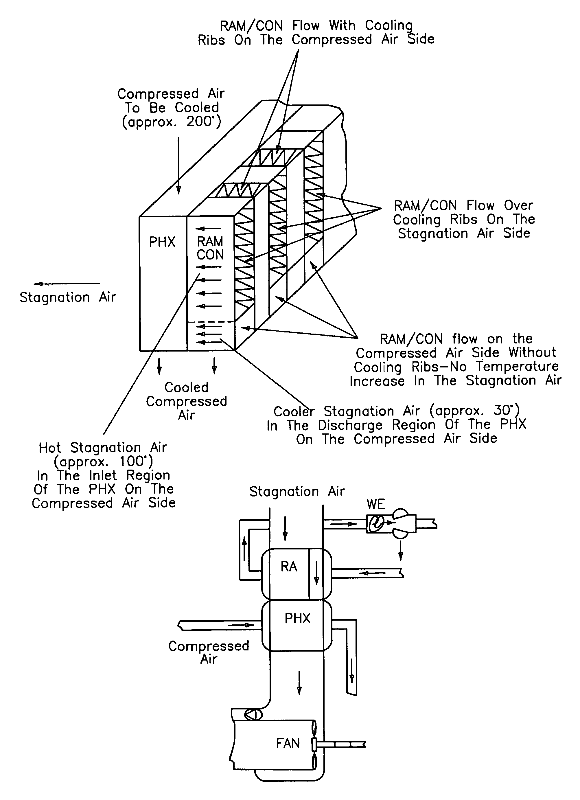
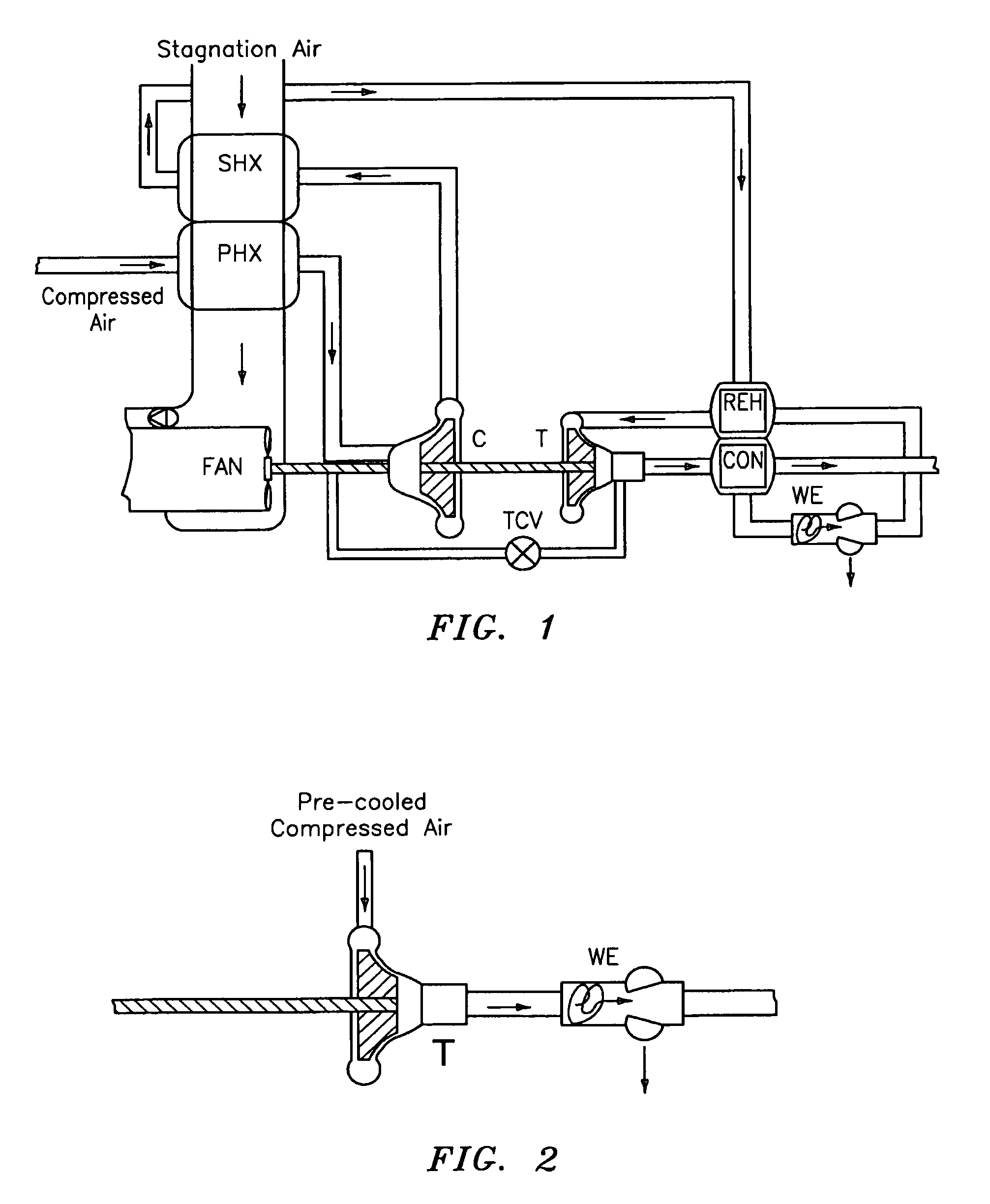
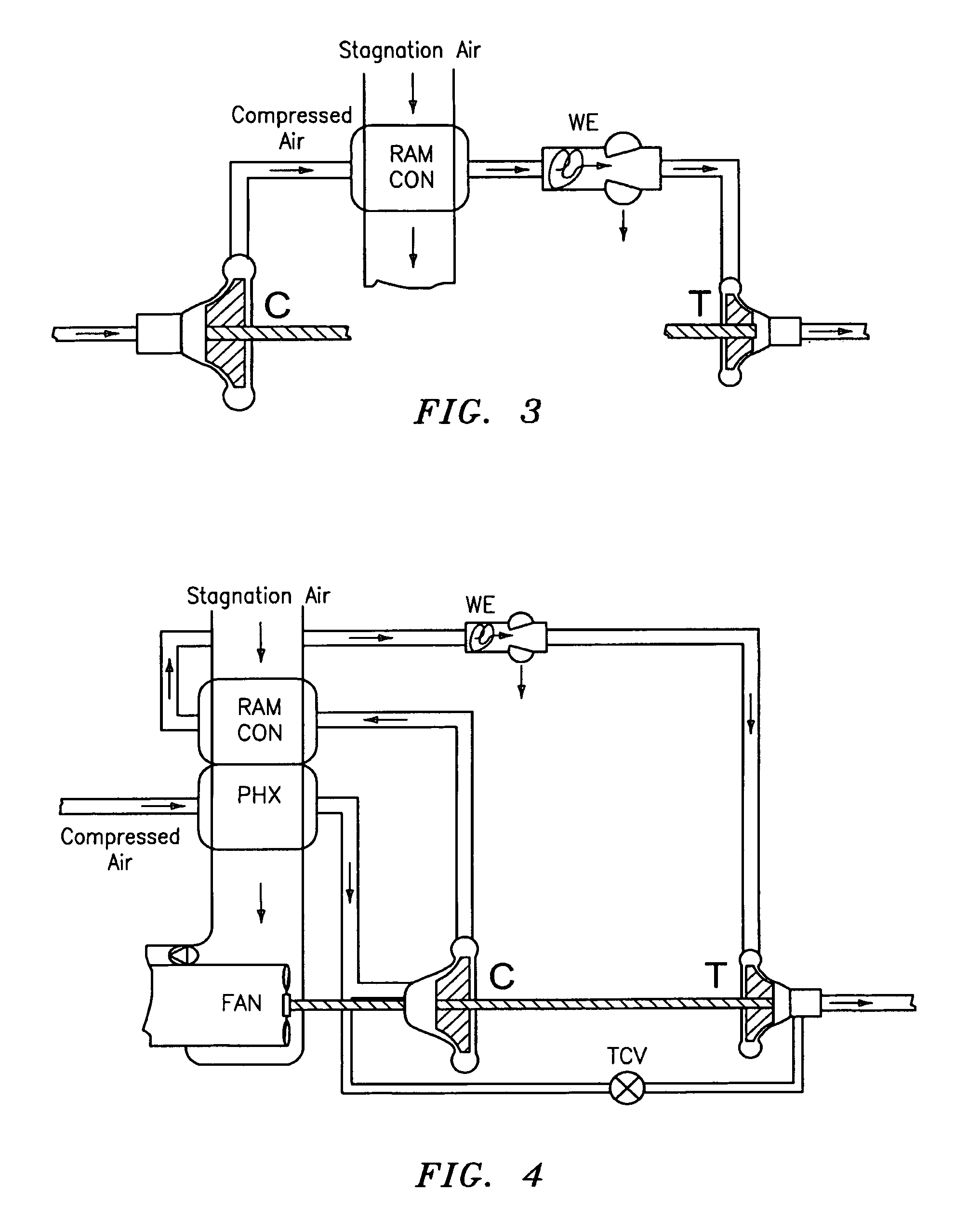
[0052]FIG. 3 shows in a section-wise representation the dehumidification of air by means of a dehumidification system in accordance with the invention comprising a compressor C, a turbine T as well as a RAM heat exchanger or condenser RAM CON (RAM heat exchanger) interposed therebetween and a water separator WE. The compressed air which is as a rule removed from the engines or auxiliary power units of an aeroplane is supplied to the compressor C and further compressed therein. The air is subsequently led through the RAM heat exchanger RAM COM and cooled hereby. Stagnation air or, in ground operation of the aeroplane, ambient air serves as the cooling air. The compressed air is cooled and humidity condensed thereby in the RAM heat exchanger RAM CON. The condensate is separated up to almost 100% in the downstream water separator WE. The air is subsequently led through the turbine, expanded and cooled here and supplied to the mixing chamber disposed upstream of the cabin. The compresso...


PUM


Abstract

The present invention relates to a system for dehumidification in air conditioners comprising an expansion stage, a condenser and comprising a water separator disposed upstream of the expansion stage. A dehumidification system with reduced system construction volume, reduced weight and increased reliability and improved system efficiency at lower cost is formed in accordance with the invention in that the condenser is formed by a heat exchanger (RAM heat exchanger) cooled with ambient air or stagnation air or with another fluid, with the exception of process air, to which the compressed air to be dehumidified is fed on the compressed air side.

Description

BACKGROUND OF THE INVENTION[0001]The present invention relates to a system for air dehumidification in air conditioners, comprising an expansion stage, a condenser and comprising a water separator upstream of the expansion stage.[0002]Such systems are known in different embodiments. They serve to dehumidify the air supplied to the cabin of, for example, an aeroplane. The dehumidification of the process air is in particular necessary when the aeroplane is at low flight altitude or when the air conditioner is running in ground operation. In all known systems, cold turbine discharge air is used indirectly or directly for this high pressure or low pressure dehumidification process.[0003]FIG. 1 shows such a dehumidification system in accordance with the prior art. It is a dehumidification process with indirect use of the turbine discharge air. With the dehumidification system shown here, pre-compressed compressed air flows through the primary heat exchanger PHX and is subsequently furthe...

Claims


Application Information

Patent Timeline
Patent Type & Authority Patents(United States)
IPC IPC(8): F25D9/00B64D13/06F24F3/14F25B9/00
CPCB64D13/06F24F3/14B64D2013/0662Y02T50/56F25B9/004Y02T50/44Y02T50/50Y02T50/40
Inventor HAAS, JOACHIMSAUTERLEUTE, ALFRED
Owner LIEBHERR AEROSPACE LINDENBERG
Why Eureka
Try Eureka