Electrical steering assist for material handling vehicles

a technology of electric steering and material handling, applied in electrical steering, transportation and packaging, lifting devices, etc., can solve the problems of increasing the required turning force, reducing productivity, and requiring a large amount of steering force to turn the steerable wheel, so as to reduce the amount of steering effort applied by the operator

Active Publication Date: 2006-03-28
CROWN EQUIP CORP
View PDF78 Cites 234 Cited by
  • Summary
  • Abstract
  • Description
  • Claims
  • Application Information

AI Technical Summary

Benefits of technology

[0006]The present invention overcomes the disadvantages of previously known material handling vehicles by providing electrical steering assist systems that reduce the operator applied steering effort required to operate such vehicles. A handle, steering arm, or other operative steering control is coupled to a steerable wheel of a material handling vehicle. A steer drive unit including a motor is also coupled to the steerable wheel for providing steering assist such that a steering effort provided by an operator may be assisted by the steer drive unit. Preferably, the operative steering control comprises a tiller handle that is mechanically coupled to the steerable wheel so that the operator retains steering control regardless of the degree (if any) of steer assist provided by the steer drive unit.

Problems solved by technology

However, a considerable amount of steering force is required to turn the steerable wheel when the truck is either at a standstill, or traveling at slow speeds.
However, as the handle is moved into a more vertical position, such as when turning in tight spaces, the radius of the arc defined by the handle with respect to the steerable wheel becomes much smaller, which results in increasing the required turning force.
Accordingly, an operator operating a truck for a full day may become tired, which may cause productivity decreases.

Method used


Image

  • Electrical steering assist for material handling vehicles
  • Electrical steering assist for material handling vehicles
  • Electrical steering assist for material handling vehicles

Examples


Embodiment Construction

[0030]In the following detailed description of the preferred embodiments, reference is made to the accompanying drawings that form a part hereof, and in which is shown by way of illustration, and not by way of limitation, specific preferred embodiments in which the invention may be practiced. It is to be understood that other embodiments may be utilized and that changes may be made without departing from the spirit and scope of the present invention.

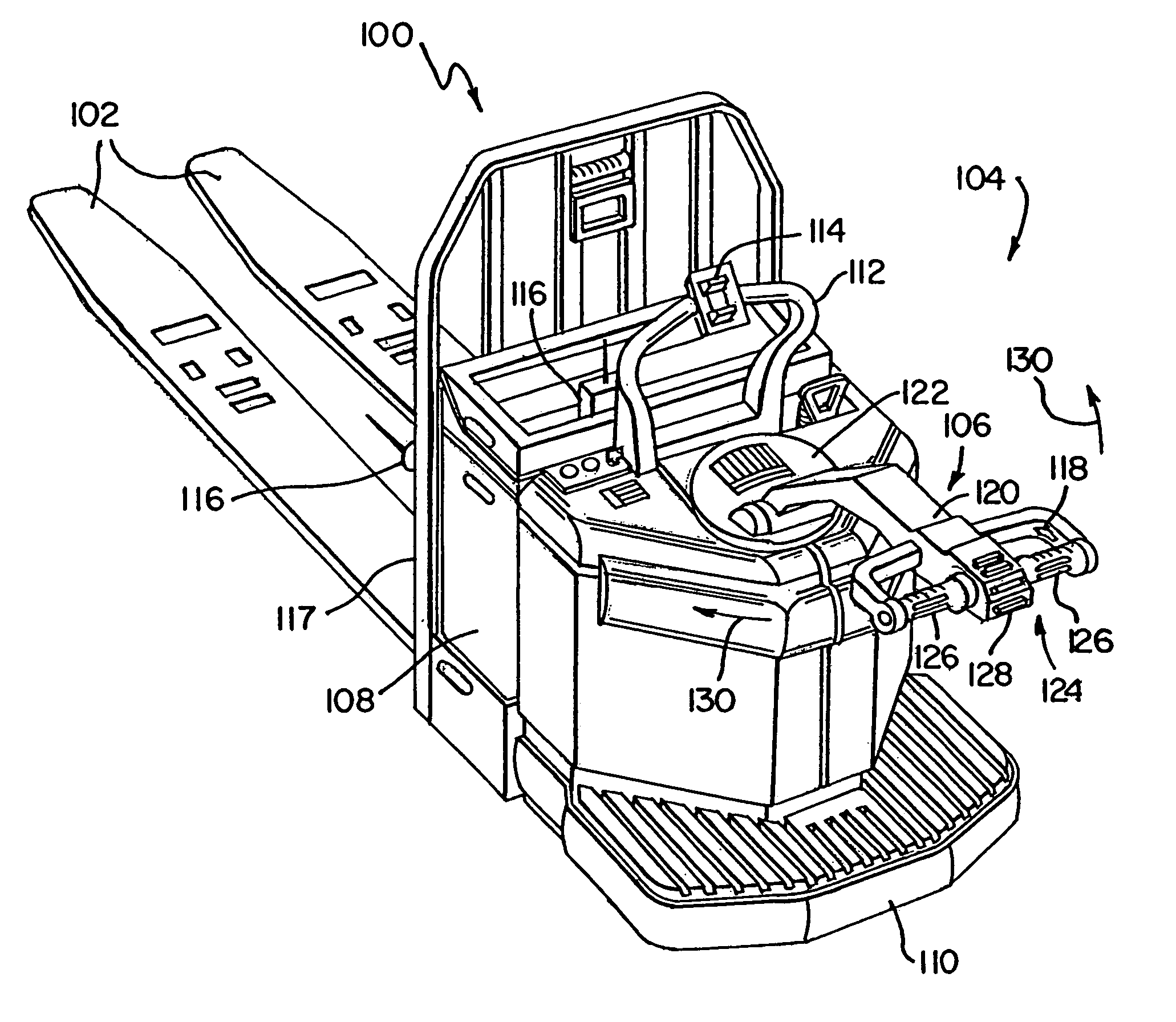
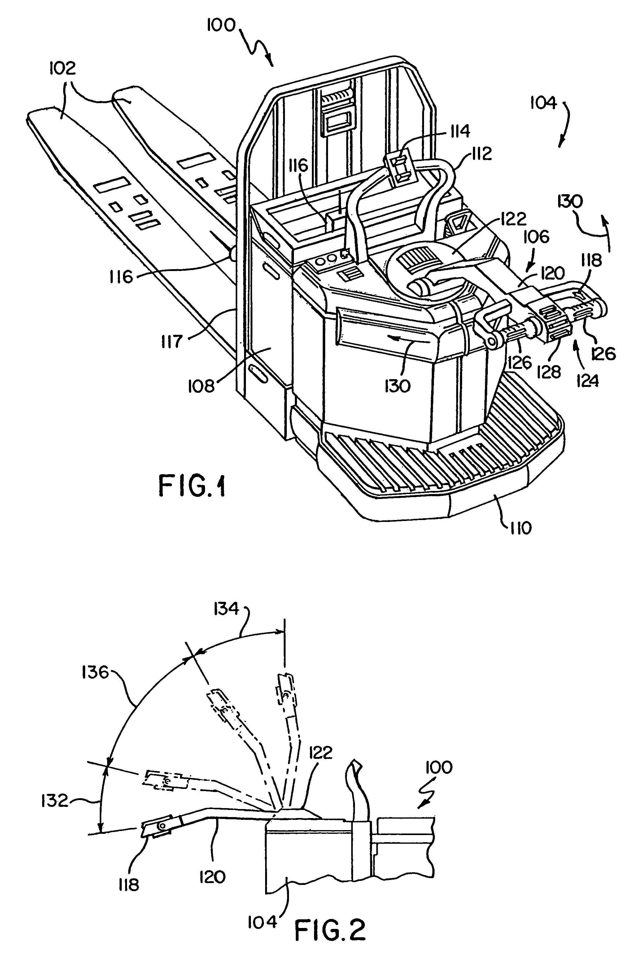
[0031]Referring initially to FIG. 1, a walkie / rider pallet truck 100 includes load carrying forks 102 that extend rearwardly from a power unit 104. The power unit 104 includes a steering control unit 106, a steerable wheel (139, see FIG. 5) that is usually located beneath the steering control unit 106 and is steered thereby, an electric traction motor (not shown) for driving the steerable wheel, and a battery compartment 108 for holding one or more batteries that supply electrical power to the truck. The power unit 104 also includes a pl...


PUM


Abstract

Electrical steering assist systems reduce the operator applied steering effort necessary to operate material handling vehicles. A steer drive unit including a motor is coupled to a steerable wheel for providing steering assist. The amount of steering assist provided by the steer drive unit is determined by a controller that receives input from one or more input sensing devices. The input sensing device(s) may include force sensors that detect an operator applied turning force. The input sensing device(s) may also detect the movement of one steering component relative to another. Further, the input sensing device(s) may include operator activated controls such as a joystick, potentiometer, switches and voice initiated commands. Input sensing device(s) may additionally be provided to detect operational parameters such as the load on the material handling vehicle, vehicle speed, or environmental conditions such as travel path obstruction detection, homing and proximity sensing.

Description

BACKGROUND OF THE INVENTION[0001]The present invention relates in general to material handling vehicles such as walkie / rider pallet trucks commonly used for picking stock in large warehouses and, more particularly, to systems and methods for providing steering assistance on such vehicles.[0002]A walkie / rider pallet truck includes generally, a set of load carrying forks, a power unit having at least one motor to power the truck, a steerable wheel and corresponding steering control mechanism to effect the direction of travel of the truck when in motion, and a platform onto which an operator may step and ride while controlling the truck. The steering control mechanism normally includes a movable steering arm, referred to as a tiller handle, which is mechanically coupled to the steerable wheel. The tiller handle includes the operational controls necessary for operating the truck, such as controls for raising and lowering the forks and rotatable twist grips or comparable devices for cont...

Claims


Application Information

Patent Timeline
Patent Type & Authority Patents(United States)
IPC IPC(8): B62D1/14B62B3/00B62B5/06B62D1/12B62D5/04B62D5/06B62D51/02B62D51/04B62D51/06
CPCB62B5/06B62D5/04B62D1/14B62D51/065B66F9/07568B66F9/24B62D51/04B62B5/063
Inventor GILLILAND, KEVIN ANTHONYKOEPER, JOHN IVANMANCI, LEWIS HENRYSNYDER, RHETT EUGENEWETTERER, GEORGE ROBERT
Owner CROWN EQUIP CORP
Why Eureka
Try Eureka