Turbulent flow drag reduction

a technology of turbulence and flow, applied in the direction of air flow influencers, machines/engines, transportation and packaging, etc., can solve the problem of fluid flow oscillation in the generally opposite direction, and achieve the effect of reducing the drag of objects

Inactive Publication Date: 2006-03-28
AIRBUS OPERATIONS LTD
View PDF14 Cites 36 Cited by
  • Summary
  • Abstract
  • Description
  • Claims
  • Application Information

AI Technical Summary

Benefits of technology

[0010]It is an object of the present invention to provide an arrangeme

Problems solved by technology

Driving the first and second electrodes alternately may cause plasma generation alternately at adjacent elec

Method used


Image

  • Turbulent flow drag reduction
  • Turbulent flow drag reduction
  • Turbulent flow drag reduction

Examples


Embodiment Construction

[0026]In the drawings, like elements are generally designated with the same reference numerals.

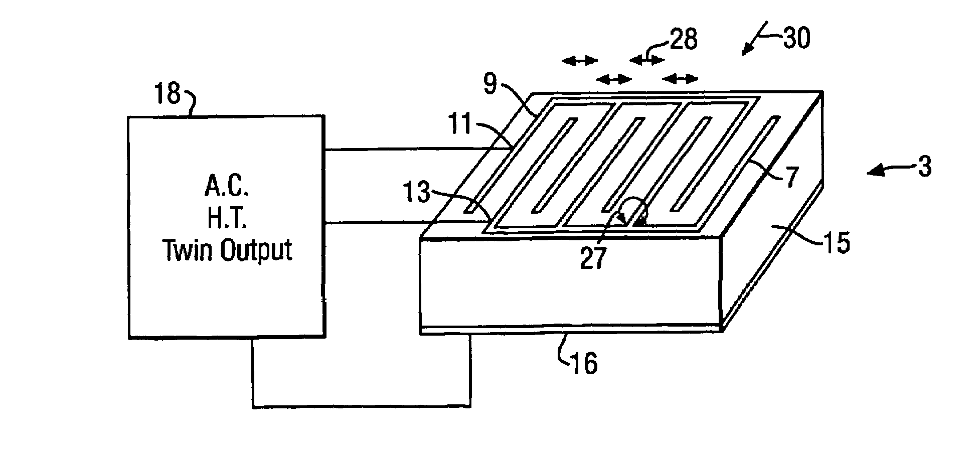
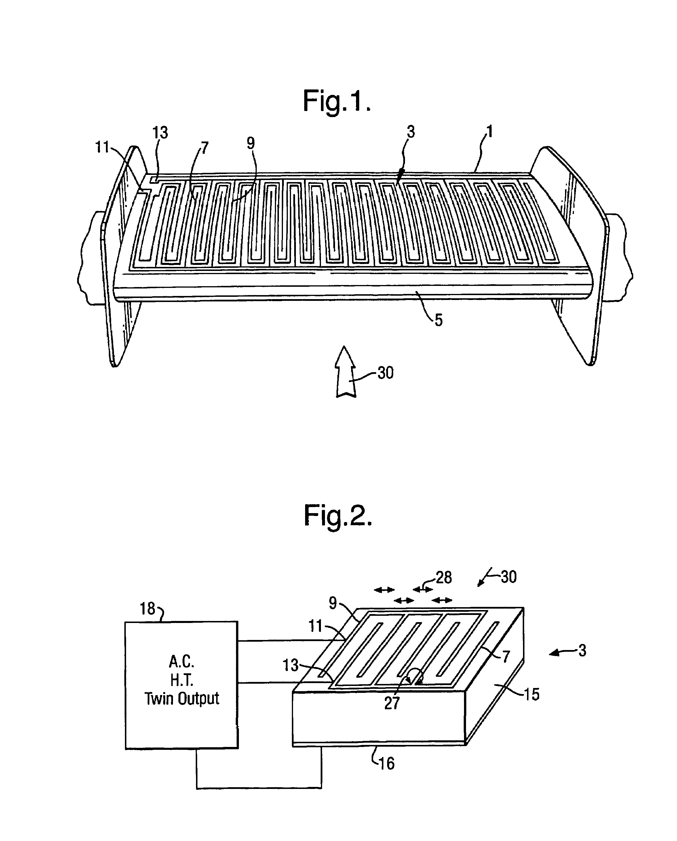
[0027]FIG. 1 shows a wing model 1 to which an electrode assembly 3 in accordance with the present invention is attached. The leading edge of the wing 1 is designated 5.

[0028]The electrode assembly 3 comprises first and second electrodes 7 and 9.

[0029]The electrodes 7 and 9 are similar in shape, and have a generally comb-like structure. Each electrode 7 and 9 comprises a plurality of parallel, vertically extending (in FIG. 1) fingers which are connected by a horizontal (in FIG. 1) strip. The fingers and the strip of each electrode 7 and 9 are integrally formed with one another. The first electrode 7 has a terminal 11 for connection to a power supply and second electrode 9 has a terminal 13 for connection to a power supply.

[0030]In the drawings only a limited number of electrode “fingers” are shown, for the sake of clarity. It will be understood that many more fingers would be employed in an...


PUM


Abstract

The present invention relates to apparatus for influencing fluid flow over a surface, and more particularly, but not exclusively, to turbulent boundary layer flow drag reduction for an aircraft. The present invention provides such apparatus including a plasma generator comprising first and second spaced-apart independently controllable electrodes operable to cause a change in direction of the flow of the fluid over the surface.

Description

[0001]This application is the US national phase of international application PCT / GB02 / 01444 filed 26 Mar. 2002, which designated the US. PCT / IB02 / 01444 claims priority of GB Application No. 0108740.2 filed 06 Apr. 2001. The entire contents of these applications are incorporated herein by reference.BACKGROUND OF THE INVENTION[0002]1. Field of the Invention[0003]The present invention relates to apparatus for influencing fluid flow over a surface, and more particularly, but not exclusively, to turbulent boundary layer flow drag reduction for an aircraft.[0004]2. Discussion of Prior Art[0005]The boundary layer is a thin layer of fluid (air) that forms, for example, on an aircraft wing during flight adjacent to the surface of the wing in which viscous forces exert an influence on the motion of the fluid and in which the transition between still air and the wing's velocity occurs. Boundary layer control techniques are known where the airflow in the boundary layer is modified to increase a...

Claims


Application Information

Patent Timeline
IPC IPC(8): B64C23/00B64C21/00B64C23/04F15D1/12
CPCB64C23/005B64C23/04F15D1/12F05D2270/172B64C2230/12Y02T50/166B64C2230/02Y02T50/10
Inventor SCOTT, SIMON JJOHNSON, GRAHAM ATHORNTON, EDWARD
Owner AIRBUS OPERATIONS LTD
Why Eureka
Try Eureka