
Support device for vertebral fusion

a support device and vertebral technology, applied in the field of vertebral fusion support devices, can solve the problems of failure to fuse, loss of disc height, recurrence of often very painful symptoms, etc., and achieve the effect of increasing the success rate of fusion

Inactive Publication Date: 2006-03-28
BRAU SALVADOR A +1
View PDF4 Cites 66 Cited by
  • Summary
  • Abstract
  • Description
  • Claims
  • Application Information

AI Technical Summary

Benefits of technology

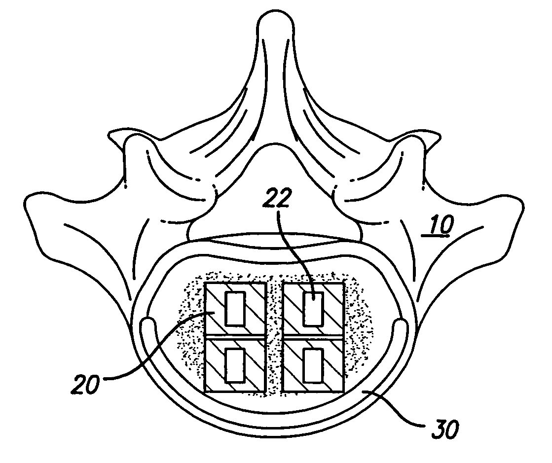
[0007]The present invention solves the problems encountered in ALIF and avoids the problems of 360 degree fusions, because it requires only one operation and uses an anterior approach. The invention acts as a spacer placed around the threaded devices used in ALIF. Once inserted, the invention takes advantage of the strength of the apophyseal ring of the fused vertebrae. After allowing 0.5 to 1.0 mm of subsidence on each vertebral end plate, the device then shares the load at the strongest part of the vertebral body, the apophyseal ring. Further subsidence is prevented and the successful fusion rate is increased. This makes the anterior-only approach, or ALIF, acceptable as a stand-alone construct for one or two levels of vertebral fusion, thus eliminating the need for a 360 degree fusion, with separate anterior and posterior operations.

Problems solved by technology

This subsidence, or slow insinuation of the threaded devices into the vertebral bodies, has resulted in lost disc height, which in some patients has resulted in the failure to fuse and the recurrence of often very painful symptoms.
This typically results in the threaded devices being placed entirely on softer bone, which is more prone to result in subsidence.
Most threaded devices in use today are placed inside of the apophyseal ring and fail to take advantage of its strength.
The principal disadvantage of 360 degree fusions is that the patient then needs two separate operations, either on the same day or in two separate stages.
There are other problems as well.
Although 360 degree fusions offer almost 100 percent fusion rates, there is not 100 percent satisfaction on the part of the patients.
The most frequent and important cause of patient dissatisfaction occurs because the posterior portion of the operation causes significant destabilization of the back muscles, which are essential for improved health of the patient's back.
This, in turn, would result in earlier resumption of physical activity and return to work.
No devices or surgical methods in use at the present time can overcome the various problems associated with either ALIF or 360 degree fusion.
This device, however, is not designed to take advantage of the apophyseal ring and thus fails to use it as a source of stability and strength.

Method used


Image

  • Support device for vertebral fusion
  • Support device for vertebral fusion
  • Support device for vertebral fusion

Examples


Embodiment Construction

[0024]The present invention is a novel device, system, and method designed to provide supplemental vertebral body end plate support for devices placed in the anterior lumbar region, such as threaded interbody fusion cages or bone dowels. The present invention generally contemplates two embodiments. One, an allograft, is made from an actual vertebral body. The other embodiment is fabricated from man-made materials such as metal, plastic, or composites.

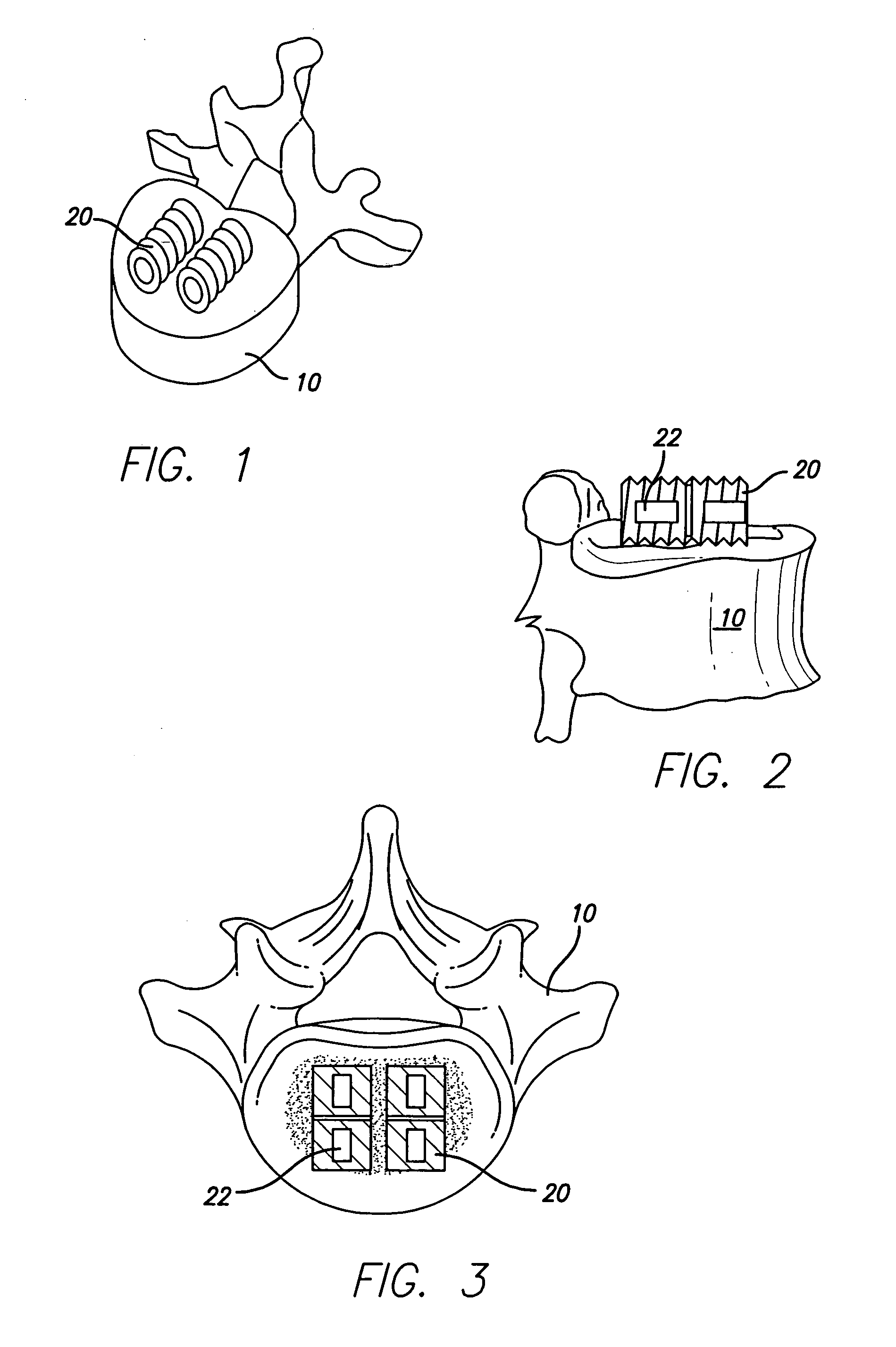
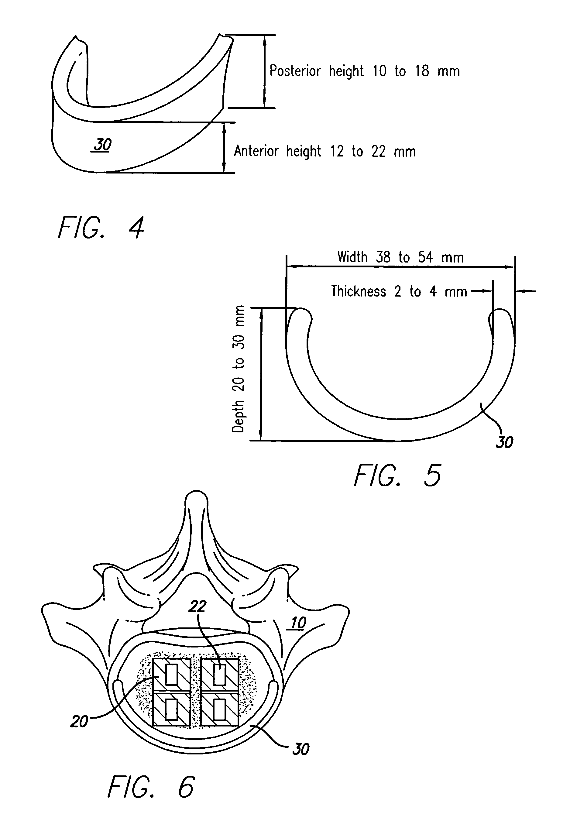
[0025]Preliminarily, the surgeon will effectively perform an ALIF, typically installing a first support device such as a pair of threaded cages or bone dowels. FIGS. 1, 2, and 3 depict different views of a vertebral body 10 with prior art cages 20 mounted on the vertebral body 10. Typically such cages contain open spaces 22 that permit bone growth throughout cage 20 for a stronger and more stable fusion. After the surgeon installs the cages, dowels, or other such support 20, he will then install a second support. One embodiment of the s...


PUM


Abstract

A support for vertebral fusion prevents subsidence and eliminates the need for posterior surgery and instrumentation. The support is constructed from cadaveric vertebrae or an implantable man-made material. One embodiment is a U-shaped metal support that rests on the apophyseal ring of the vertebrae, with the open portion of the U facing the patient's posterior. The metal support is then connected to a previously placed threaded cage or bone dowel such as that used in anterior lumbar interbody fusion (ALIF).

Description

CROSS-REFERENCE TO RELATED APPLICATION[0001]This application claims the benefit of and is a continuation-in-part of Provisional Application No. 60 / 399,584, filed Jul. 30, 2002.BACKGROUND OF THE INVENTION[0002]This invention relates to the maintenance of an adequate disc height, by the prevention of subsidence, following Anterior Lumbar Interbody Fusion (ALIF), which typically uses threaded metal cages or threaded bone dowels.[0003]Anterior Lumbar Interbody Fusion (ALIF) using threaded devices such as cages and bone dowels has been in use for over ten years. Initially, threaded cages or dowels were expected to act as a stand-alone device that would promote fusion and maintain disc height without the need for posterior surgery and instrumentation of the spine. In spite of fusion rates better than 90 percent for single level fusion and 65 percent for two-level fusion, significant subsidence has been observed on follow-up X-rays at varying times following the procedure. This subsidence,...

Claims


Application Information

Patent Timeline
IPC IPC(8): A61F2/44A61F2/00A61F2/28A61F2/30
CPCA61F2/446A61F2/28A61F2002/30131A61F2002/30405A61F2002/30578A61F2002/30785A61F2310/00359A61F2002/448A61F2220/0025A61F2230/0013A61F2310/00023A61F2310/00029A61F2002/3085
Inventor BRAU, SALVADOR A.SCHIFFMAN, MICHAEL L.
Owner BRAU SALVADOR A
Learn More