Radiation ray detector and method of manufacturing the detector

Inactive Publication Date: 2006-03-28
HAMAMATSU PHOTONICS KK
View PDF16 Cites 28 Cited by
  • Summary
  • Abstract
  • Description
  • Claims
  • Application Information

AI Technical Summary

Benefits of technology

[0010]According to the present invention, a light receiving section that has a large image-pickup area is formed by arranging the light receiving sections of the plurality of image sensor panels so as to adjoin each other. A transparent film is wholly formed on the light receiving sections while flattening the surface thereof, and a scintillator is formed directly on the film, whereby a uniform scintillator can be formed, and a detector having uniform image prope

Problems solved by technology

However, there is a problem that a scintillator is liable to separate from a boundary (a joint)with an adjoining detecting element when a plurality of detecting elements are arranged to

Method used


Image

  • Radiation ray detector and method of manufacturing the detector
  • Radiation ray detector and method of manufacturing the detector
  • Radiation ray detector and method of manufacturing the detector

Examples


Embodiment Construction

[0019]Preferred embodiments of the present invention will hereinafter be described in detail with reference to the accompanying drawings. To facilitate the comprehension of the explanation, the same reference numerals denote the same parts, where possible, throughout the drawings, and a repeated explanation will be omitted. Additionally, the size and shape of each component in each drawing are not necessarily the same as the actual ones, and some components are magnified in size and in shape in order to facilitate the understanding thereof.

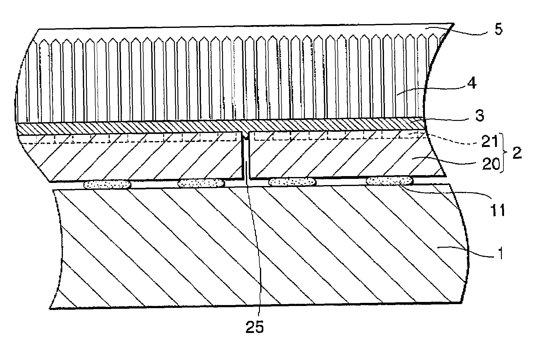
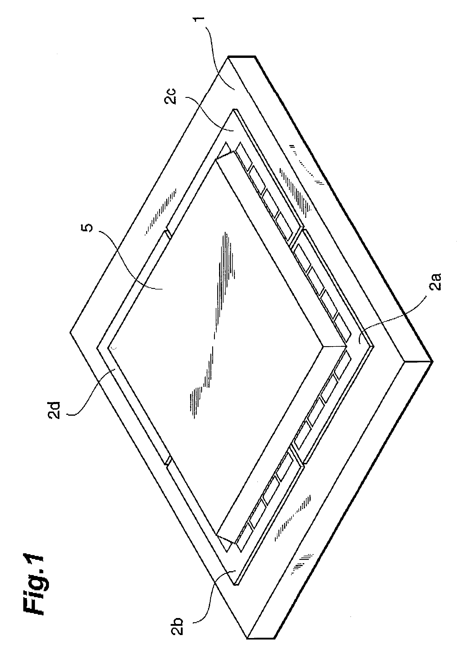
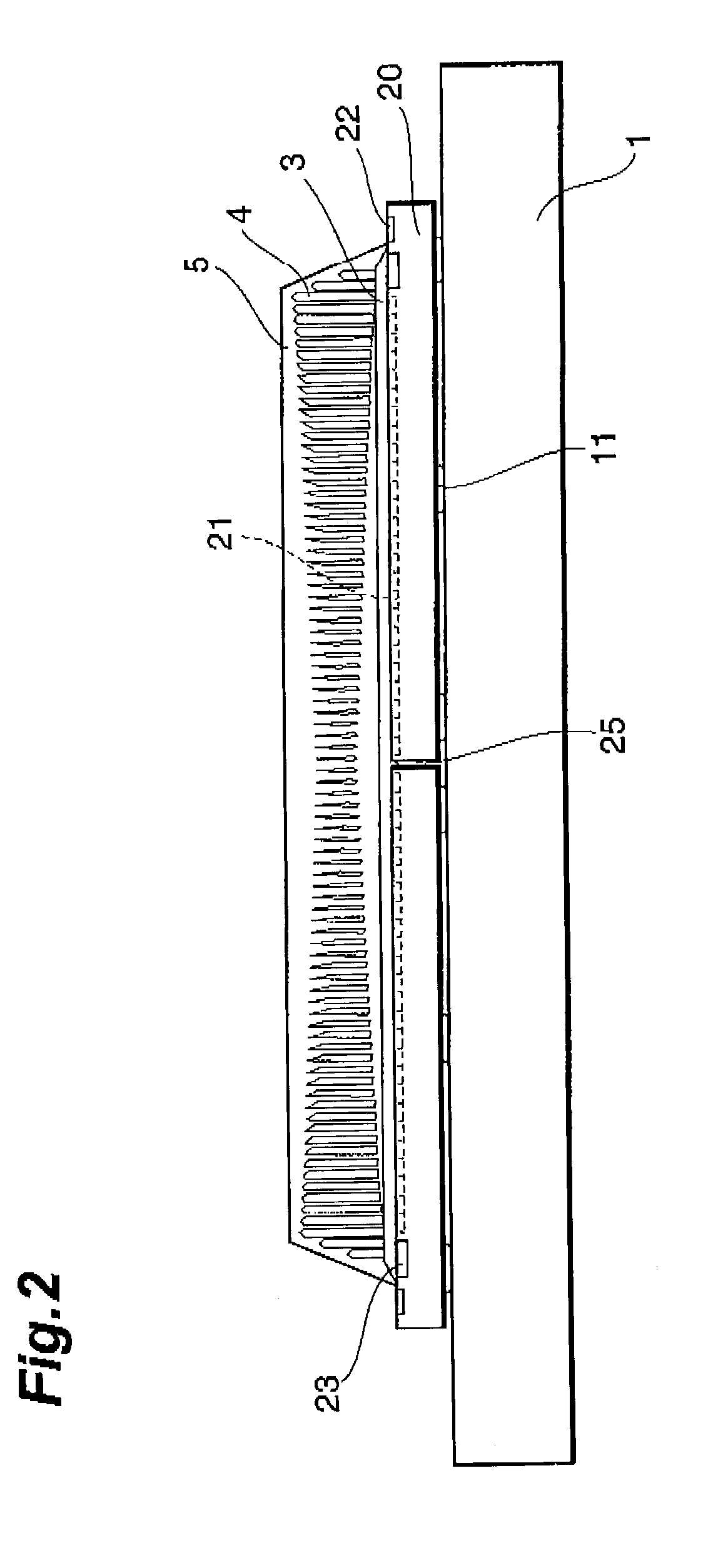
[0020]FIG. 1 is a perspective view showing an embodiment of the radiation detector according to the present invention, FIG. 2 is a sectional view thereof, and FIG. 3 is a partially enlarged view of FIG. 2. The radiation detector 100 in this embodiment is formed by disposing solid-state image sensing devices 2a to 2d, which are four image sensor panels, in 2×2 array on a ceramic base 1. Each of the solid-state image sensing devices 2a to 2d is fixe...


PUM

PropertyMeasurementUnit
Lengthaaaaaaaaaa
Lengthaaaaaaaaaa
Lengthaaaaaaaaaa

Abstract

The light receiving sections of solid-state image sensing devices (2a and 2b) are disposed on a base (1) to adjoin each other, and are fixed with an adhesive resin (11). A transparent film (3) is formed on the light receiving sections so as to wholly cover a gap (25) and have a flat surface on which a layer of a scintillator (4) is formed.

Description

TECHNICAL FIELD[0001]This invention relates to a radiation detector, and, more particularly, to a radiation detector constructed by arranging a plurality of image sensors so as to take a radiation image having a large area, and relates to a method for manufacturing the radiation detector.BACKGROUND ART[0002]An X-ray image sensor using a CCD, in place of an X-ray photosensitive film, has been widely employed as an X-ray diagnostic instrument for medical use. In such a radiation imaging system, two-dimensional image data by radiation is obtained as an electrical signal by use of a radiation detector that has a plurality of pixels, and an X-ray image is displayed on a monitor by processing the signal with a processor. A typical radiation detector has a configuration in which a scintillator is disposed on photodetectors arranged one-dimensionally or two-dimensionally, and incident radiations are transformed by the scintillator into light, and are detected.[0003]In this type of radiation...

Claims


Application Information

Patent Timeline
IPC IPC(8): G01T1/20H01L31/02G01J5/28G01T1/29
CPCG01T1/2018Y10T29/49007G01T1/20187G01T1/20189
Inventor HOMME, TAKUYATAKABAYASHI, TOSHIO
Owner HAMAMATSU PHOTONICS KK
Why Eureka
Try Eureka