Transmission line input structure test probe

a technology of input structure and transmission line, which is applied in the direction of resistance/reactance/impedence, instruments, measurement devices, etc., can solve the problems of reducing the measured voltage, affecting the measurement of dynamic timing characteristics, and the high-impedance test probe is not suited for high-frequency measurements

Inactive Publication Date: 2006-03-28
TELEDYNE LECROY
View PDF22 Cites 127 Cited by
  • Summary
  • Abstract
  • Description
  • Claims
  • Application Information

AI Technical Summary

Problems solved by technology

This reduces the measured voltage and affects measurements of dynamic timing characteristics, such as pulse rise time.
A high-impedance test probe, however, is not suited for high-frequency measurements because of the relatively high value of its input capacitance.
One limitation of the low-impedance test probe is that it may be used only at a test point with a relatively low source resistance.
Another disadvantage is that the low-impedance test probe is a single ended test probe.
An additional limitation of the low-impedance test probe is that the frequency is limited to the resonant frequency of the probe input capacitance in series with the ground lead inductance.
One limitation of the active test probe, however, is that it is not possible to design an amplifier with the required high input impedance at very high frequencies.
Another limitation of the active test probe is that high frequency signals can be distorted because of electromagnetic wave reflection.
This signal distortion results from the fact that as frequency increases, the input structure becomes large with respect to the electrical wavelength.
The active test probe design has additional limitations when it is used in differential test probes.
In practice, however, the difficulty of properly matching the two divider networks can be a significant limitation.
Another limitation is that high frequency signal distortion from electromagnetic wave reflection can be a significant problem when sampling two spaced-apart test points.
In this situation, it may be physically impossible to keep the input structures small with respect to the electrical wavelength.
The problem with these systems is that the tips often slide or swivel by themselves when the user does not want them to move.

Method used


Image

  • Transmission line input structure test probe
  • Transmission line input structure test probe
  • Transmission line input structure test probe

Examples


Embodiment Construction

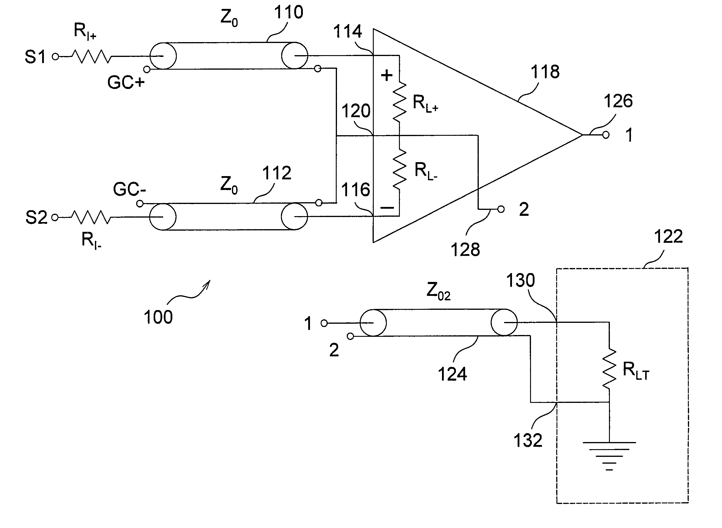
[0030]The present invention is directed to an active differential test probe with a transmission line input structure. The test probe of the present invention is advantageously described with reference to prior art test probes. FIGS. 2–5 depict several prior art test probes. FIGS. 6–9 are circuit diagrams of exemplary test probes of the present invention. FIGS. 10–18 show one preferred embodiment of matched transmission lines for a probe tip on a common substrate that may be flexible.

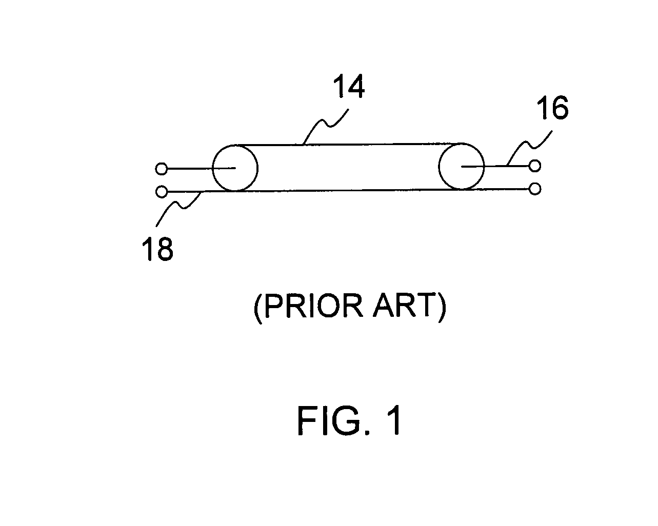
[0031]Throughout this application, reference is made to the signal conductor and the ground conductor of various transmission lines. FIG. 1 is a circuit diagram that illustrates an exemplary transmission line 14. The exemplary transmission line 14 includes a signal conductor 16 and a ground conductor 18. FIG. 1 illustrates how the signal conductor and the ground conductor of a transmission line are depicted in the remaining figures. As will be apparent to one skilled in the art, however, the transmissio...


PUM


Abstract

A differential electrical test probe tip for sensing a plurality of electric signals and generating a differential signal including an elongate common substrate having a two signal test points at one end and a differential amplifier at the second end. Two transmission lines are on the common substrate, each connecting a respective signal test point a signal input of the differential amplifier. The characteristic impedances of the two transmission lines are substantially equal. In one preferred embodiment, the common substrate is a flexible substrate. In one preferred embodiment an over-mold, which may have gaps therein, at least partially encloses the common substrate, the first transmission line, and the second transmission line.

Description

[0001]The present application is a continuation-in-part of U.S. patent application Ser. No. 10 / 261,829, U.S. Pat. No. 6,822,463 filed Sep. 30, 2002, which in turn claims the benefit under 35 USC Section 119(e) of U.S. Provisional Patent Application Ser. No. 60 / 342,974, filed Dec. 21, 2001. The present application is based on and claims priority from these applications, the disclosures of which are hereby expressly incorporated herein by reference in their entirety.BACKGROUND OF INVENTION[0002]The present invention relates to the field of electrical test probes. More particularly, the present invention relates to an active differential test probe with a transmission line input structure.[0003]An electrical signal will change when a test instrument, such as an oscilloscope, is connected to the circuit that generates the signal. For example, if a bare wire is connected between a circuit and an oscilloscope, the wire and the input circuitry of the oscilloscope effectively add a load res...

Claims


Application Information

Patent Timeline
Patent Type & Authority Patents(United States)
IPC IPC(8): G01R27/08G01R1/067
CPCG01R1/06772
Inventor JACOBS, LAWRENCE W.CAMPBELL, JULIE A.
Owner TELEDYNE LECROY
Why Eureka
Try Eureka