Video editing apparatus and editing method for combining a plurality of image data to generate a series of edited motion video image data

Active Publication Date: 2006-03-28
PANASONIC INTELLECTUAL PROPERTY CORP OF AMERICA
View PDF4 Cites 109 Cited by
  • Summary
  • Abstract
  • Description
  • Claims
  • Application Information

AI Technical Summary

Benefits of technology

[0011]The object of the present invention is thus to improve the workability and the certainty in the process of settin

Problems solved by technology

This is extremely troublesome and labor-consuming.
This also leads to a higher possibility of mistakes in the process of changing the transition effects.
The prior art non-linear editing technique imposes a heavy workload, because of the reasons discussed above.
This problem arises not only in the process of setting the transition effects but also in the process of setting cover images superimp

Method used


Image

  • Video editing apparatus and editing method for combining a plurality of image data to generate a series of edited motion video image data
  • Video editing apparatus and editing method for combining a plurality of image data to generate a series of edited motion video image data
  • Video editing apparatus and editing method for combining a plurality of image data to generate a series of edited motion video image data

Examples


second embodiment

G. Second Embodiment

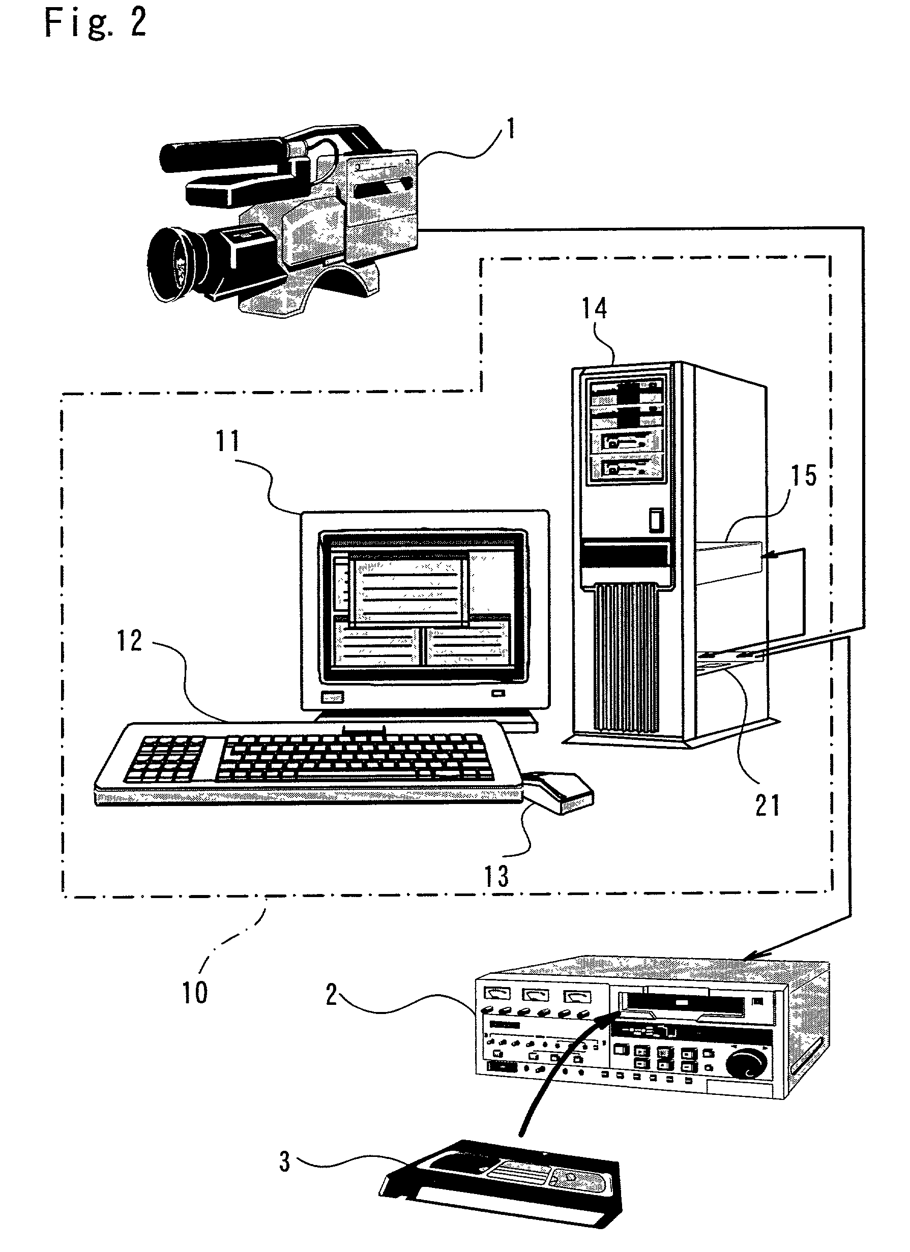
[0092]The following describes another video editing apparatus in a second embodiment of the present invention. The video editing apparatus of the first embodiment indirectly specifies the transition effect on each occasion of transition of the scene by the effect setting table 44. The video editing apparatus of the second embodiment, on the other hand, indirectly specifies a cover image to be superimposed on a main video film, for example, telop or an image presenting sponsors. The second embodiment has the same hardware structure as that of the first embodiment (see FIGS. 2 and 3), but has different functional blocks to attain the different functions as mentioned above.

[0093]FIG. 14 shows functional blocks in the video editing apparatus of the second embodiment. The differences from the first embodiment (see FIG. 4) include a cover setting table 44c used in place of the effect setting table 44, the format of data stored in an editing management data memory 43a, ...

third embodiment

H. Third Embodiment

[0102]The following describes still another video editing apparatus in a third embodiment of the present invention. The video editing apparatus of the third embodiment indirectly specifies intermediate images like advertising films, commercials, and spots to be inserted into successive video clips of a main video film. The third embodiment has the same hardware structure as that of the first embodiment (see FIGS. 2 and 3), but has different functional blocks to attain the different functions as mentioned above.

[0103]FIG. 17 shows functional blocks in the video editing apparatus of the third embodiment. The main differences from the first embodiment (see FIG. 4) is a intermediate image setting table 44d used in place of the effect setting table 44.

[0104]FIG. 18 shows an example of data stored in the intermediate image setting table 44d. In the example of FIG. 18, ‘Sponsor A’, ‘Sponsor B’, and ‘Sponsor C’ are set as intermediate image names, and two different tables...


PUM


Abstract

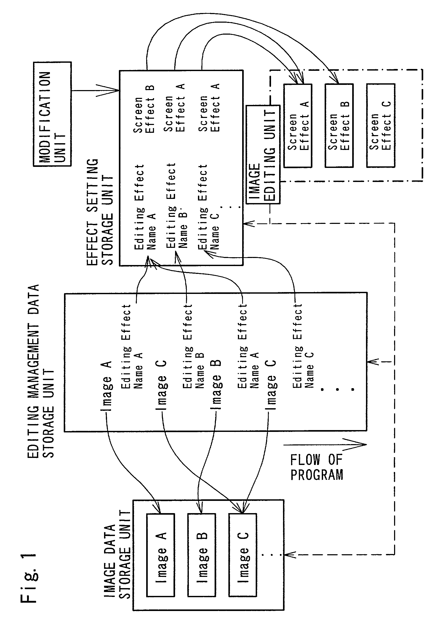
A video editing apparatus for editing electronic motion video image data utilizes an effect setting table that specifies mapping of editing effect names arbitrarily registered by the user to editing effects or screen effects, for example, transition effects between different scenes or successive video clips and insertion of captions and subtitles, executable by the video editing apparatus. In editing management data that specify a flow of a program, editing effects to be applied in respective video clip data are set indirectly by specifying the editing effect names registered in the effect setting table. Varying the mapping of the editing effect names to the editing effects enables a desired editing effect corresponding to a certain editing effect name to be collectively changed without modifying the editing management data. This arrangement desirably relieves the labor in the process of setting the editing effects and improves the certainty.

Description

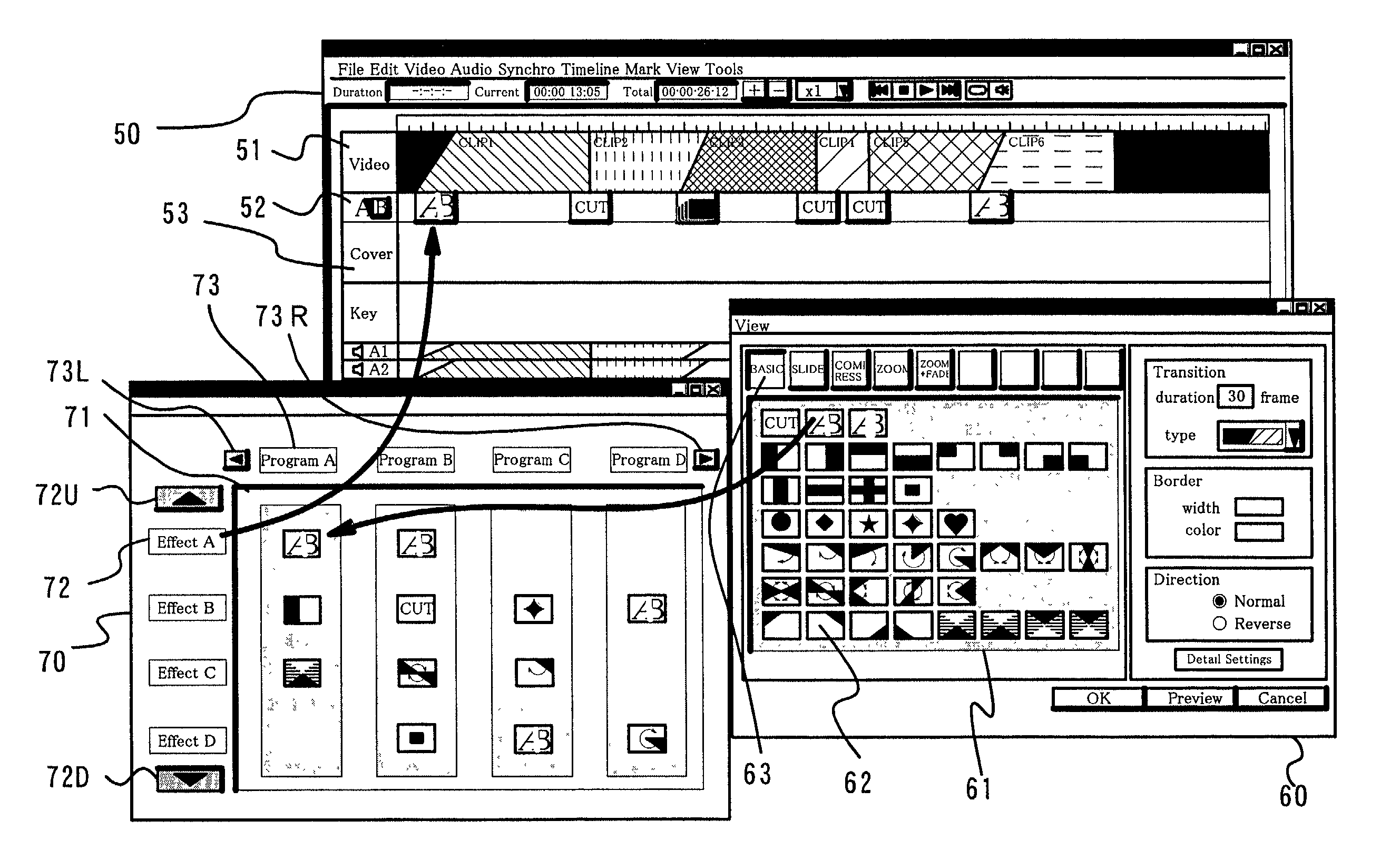
BACKGROUND OF THE INVENTION[0001]1. Field of the Invention[0002]The present invention relates to a video editing apparatus that utilizes electronic motion video image data and generates program data, for example, for television broadcasting programs.[0003]2. Description of the Related Art[0004]A technique that stores motion video images as electronic motion video image data in a hard disk and edits the electronic motion video image data to generate program data with the aid of a computer, that is, a non-linear editing technique, has been popularized recently. FIG. 20 shows a prior art process of non-linear editing. Here shows an exemplified screen display for non-linear editing that takes advantage of GUIs (graphical user interfaces).[0005]In the exemplified process of non-linear editing, an editing window PW for carrying out edition and a transition effects window EW for selecting transition effects of different scenes. Motion video images, which will be the element of program data...

Claims


Application Information

Patent Timeline
IPC IPC(8): H04N5/93
CPCG11B27/034H04N21/854H04N21/812H04N5/262
Inventor KATO, YUICHISUZUKI, MOTOSHI
Owner PANASONIC INTELLECTUAL PROPERTY CORP OF AMERICA
Why Eureka
Try Eureka