
Communications system using a satellite-based network with a plurality of spot beams providing ubiquitous coverage from two different satellites

a satellite-based network and spot beam technology, applied in the field of communication system using a satellite-based network with a plurality of spot beams providing ubiquitous coverage from two different satellites, can solve problems such as consumption of energy, and achieve the effects of saving energy, saving energy, and saving power used by satellite systems

Inactive Publication Date: 2006-03-28
HUGHES ELECTRONICS
View PDF15 Cites 43 Cited by
  • Summary
  • Abstract
  • Description
  • Claims
  • Application Information

AI Technical Summary

Benefits of technology

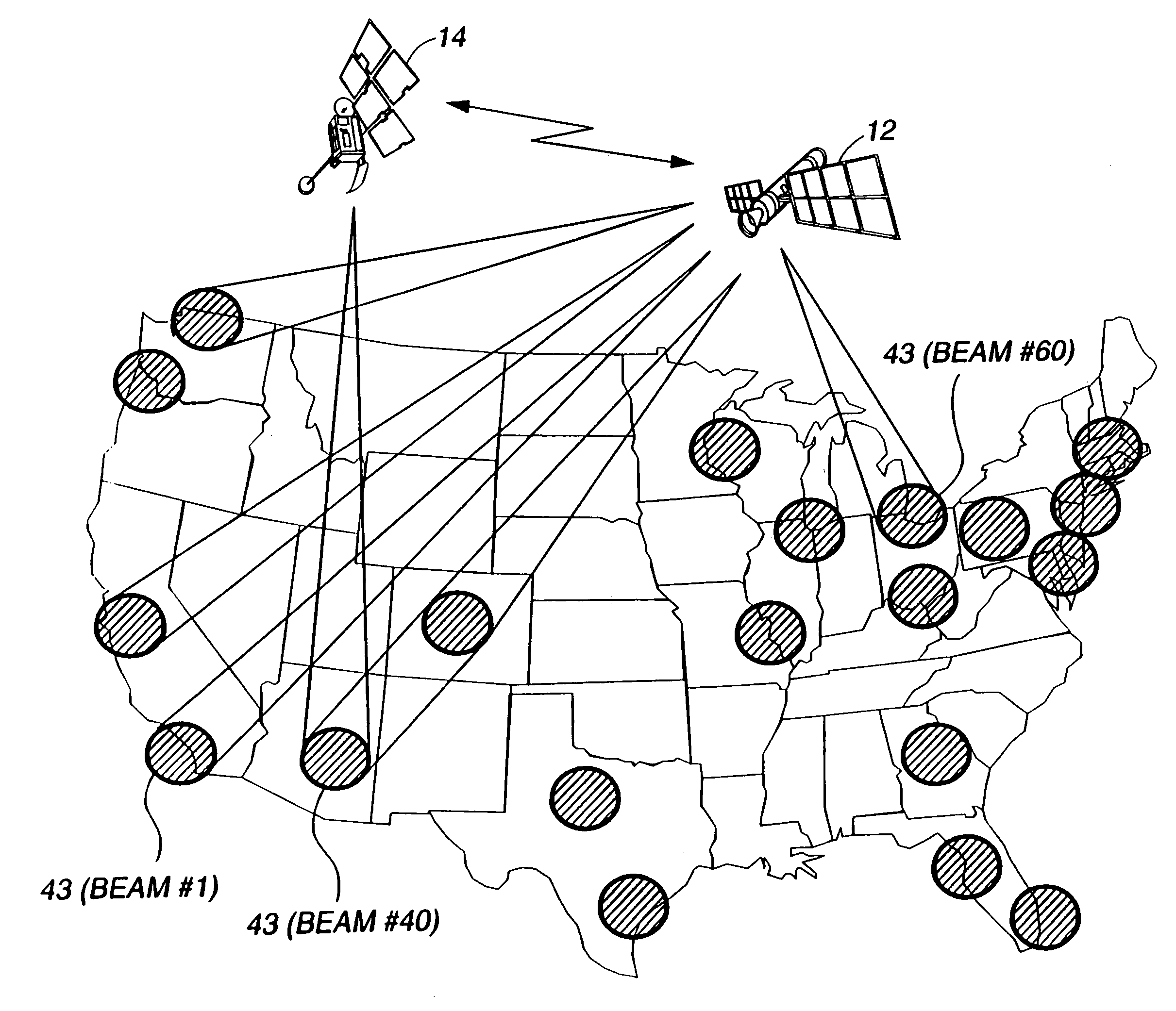
[0012]One advantage of the present invention is that power used by the satellite system may be conserved by using a routing switch that routes signals according to their desired destination. Typically, a packet switch is used to route signals. If the received beam is to be transmitted through to the same beam, the carrier frequency can be shifted and the signal returned through the same beam. These signals thus bypass the packet switch. This saves energy because the packet switch performs other operations on the signal such as demodulation, instruction reading and remodulation, each of which consumes energy. The extra functions are unnecessary if the signal is routed through the same beam.
[0013]In yet another aspect of the invention, the spot beams of two satellites may be combined on the ground to provide ubiquitous coverage over the entire land mass. If medium Earth orbit satellite orbits are used, at least two MEO satellites are in view at any one time with the preferred constellation.

Problems solved by technology

This saves energy because the packet switch performs other operations on the signal such as demodulation, instruction reading and remodulation, each of which consumes energy.

Method used


Image

  • Communications system using a satellite-based network with a plurality of spot beams providing ubiquitous coverage from two different satellites
  • Communications system using a satellite-based network with a plurality of spot beams providing ubiquitous coverage from two different satellites
  • Communications system using a satellite-based network with a plurality of spot beams providing ubiquitous coverage from two different satellites

Examples


Embodiment Construction

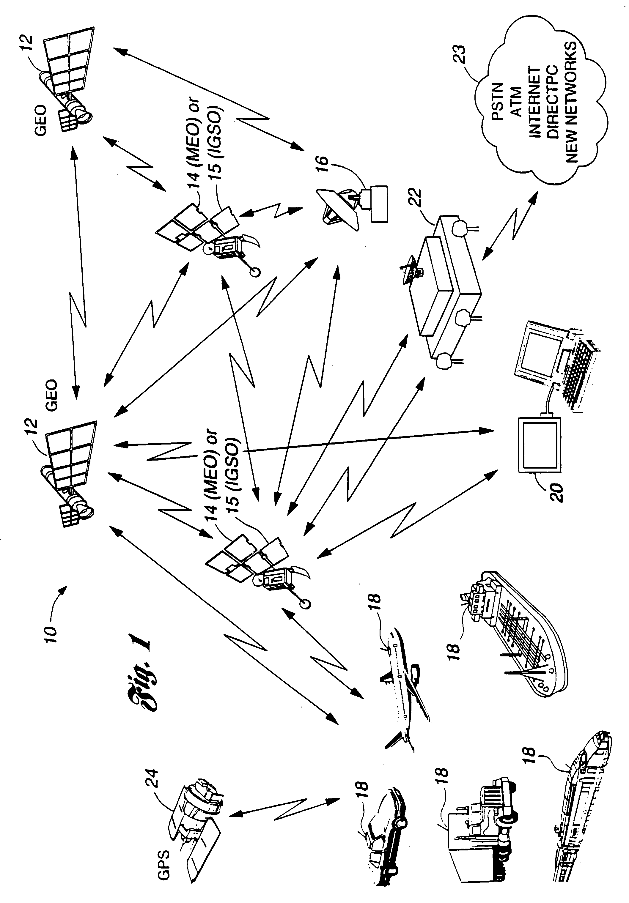
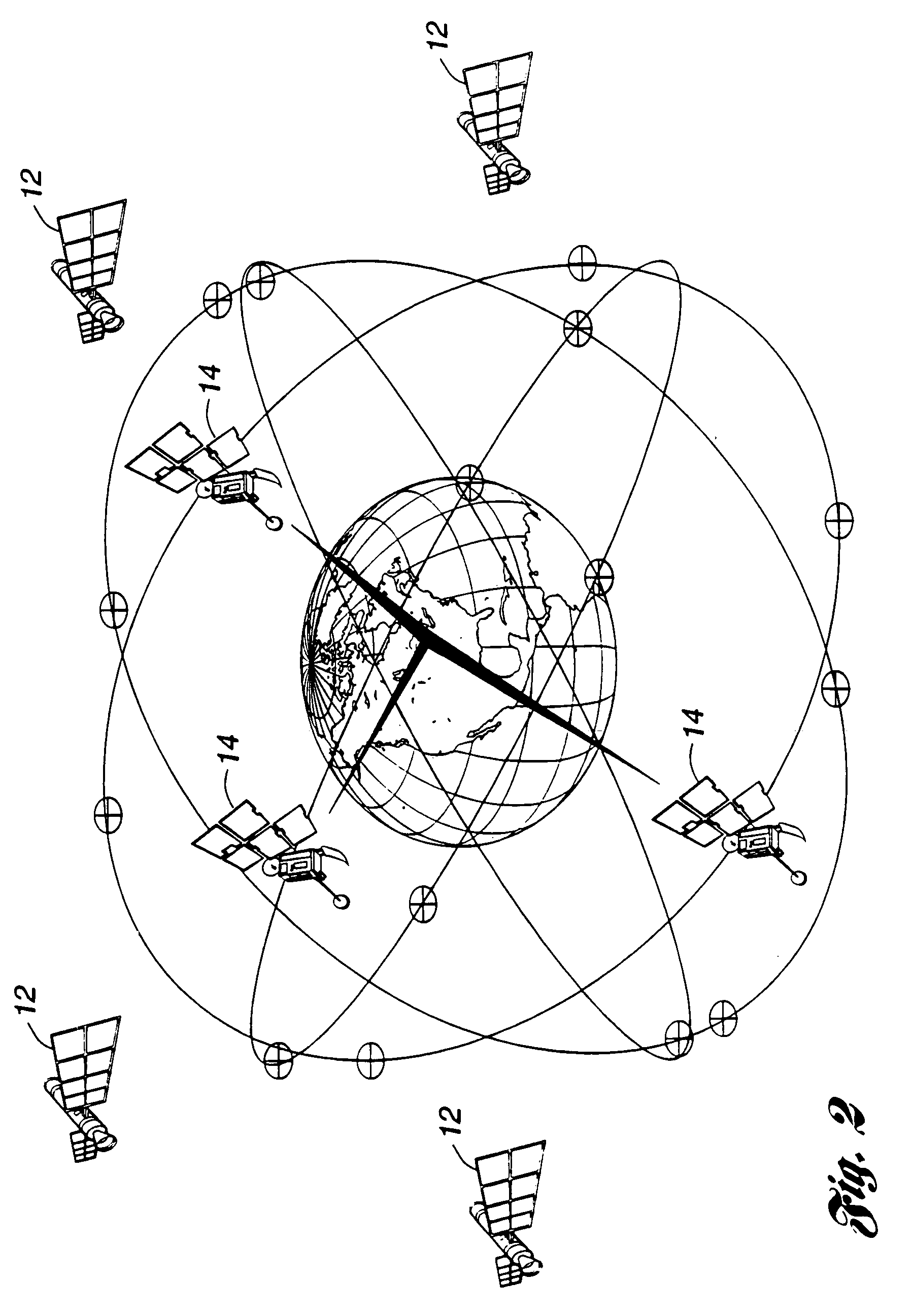
[0028]Referring first to FIG. 1, a communications system 10 with a typical geometry for practicing the present invention is diagrammatically illustrated. In general, the system 10 includes a plurality of communications satellites both in geostationary earth orbit (GEO) 12 and in non-geostationary earth orbit (NGSO) 14 and 15. A system also includes a ground station 16 for controlling and maintaining operation of satellites 12, 14, and 15, as well as user terminals in the form of either mobile devices 18 or portable devices 20. The system 10 also includes a system access node 22 situated in each region serviced by satellites 12, 14, and 15 which is connected by trunk lines to one of several possible networks 23, e.g., local or long distance public switched telephone networks (PSTN), Asynchronous Transfer Mode (ATM) networks, the Internet, DirecPC (a satellite-based Internet access system), or any other data or voice networks. Still further, the system 10 uses information from at leas...


PUM


Abstract

A satellite-based communications system operating at high data rates includes a plurality of satellites each having uplink and downlink antennas for transmitting and receiving a plurality of signals utilizing a plurality of spot beams to and from a plurality of coverage areas at a predetermined range of frequencies. The system can include, or be combined with, other systems to enable increased capacity over high population areas and ubiquitous coverage over lower population areas. A portable antenna assembly can be coupled to a user's portable or mobile electronic device for coupling the electronic device directly to a satellite. A routing switch provides routing and switching on-board the satellite and routes signals according to their desired destination.

Description

CROSS-REFERENCE TO RELATED APPLICATIONS[0001]This application is a continuation-in-part of U.S. patent application Ser. No. 08 / 867,197, entitled “Method and System For Providing Wideband Communications To Mobile Users in a Satellite-based Network” filed on Jun. 2, 1997 Now U.S. Pat. No. 6,032,041, the subject matter of such application being incorporated herein by reference.TECHNICAL FIELD[0002]This invention relates to methods and systems for providing broadband communications to mobile users in a satellite-based communications network.BACKGROUND OF THE INVENTION[0003]Wired terrestrial systems offer communications at high data rates, but only while the user is sitting behind a computer. As soon as the user goes to a conference room, walks outside an office building, gets into a car, or drives to a park, the connection is lost. Mobility, however, can be supported in one of two ways, namely terrestrial-based wireless networks or satellite-based communications systems.[0004]Terrestria...

Claims


Application Information

Patent Timeline
IPC IPC(8): H04Q7/20
CPCH04B7/2041
Inventor WESEL, ELLEN K.
Owner HUGHES ELECTRONICS
Learn More