
Electric load management center including gateway module and multiple load management modules for distributing power to multiple loads

a technology of load management module and gateway module, which is applied in the direction of vehicle position/course/altitude control, process and machine control, instruments, etc., can solve the problems of limited local control functionality and flexible configuration of sspcs, and the module solid state power controller with microcomputers is limited to basic on/off control of power switches

Active Publication Date: 2006-03-28
HONEYWELL INT INC
View PDF69 Cites 46 Cited by
  • Summary
  • Abstract
  • Description
  • Claims
  • Application Information

AI Technical Summary

Benefits of technology

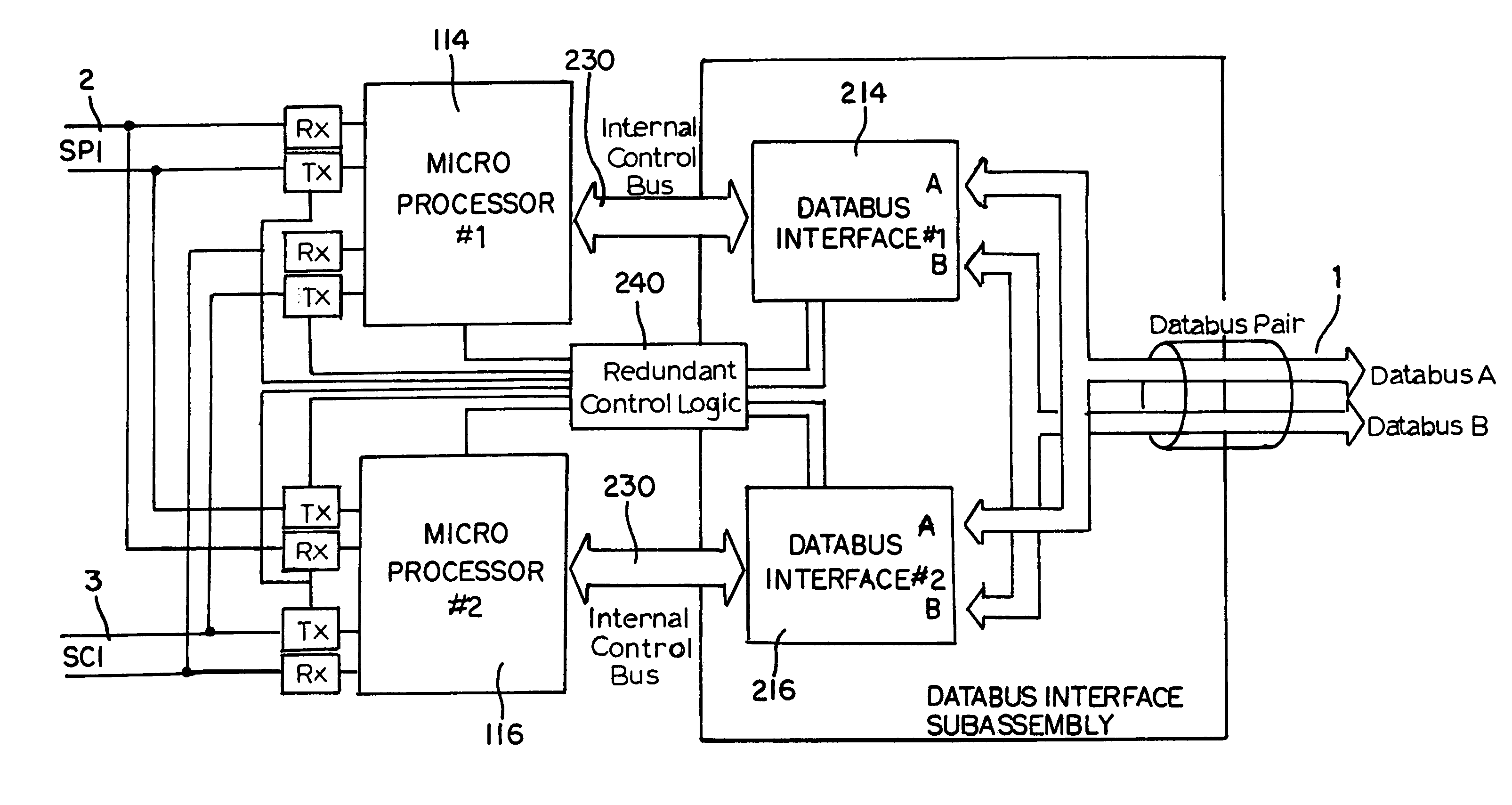
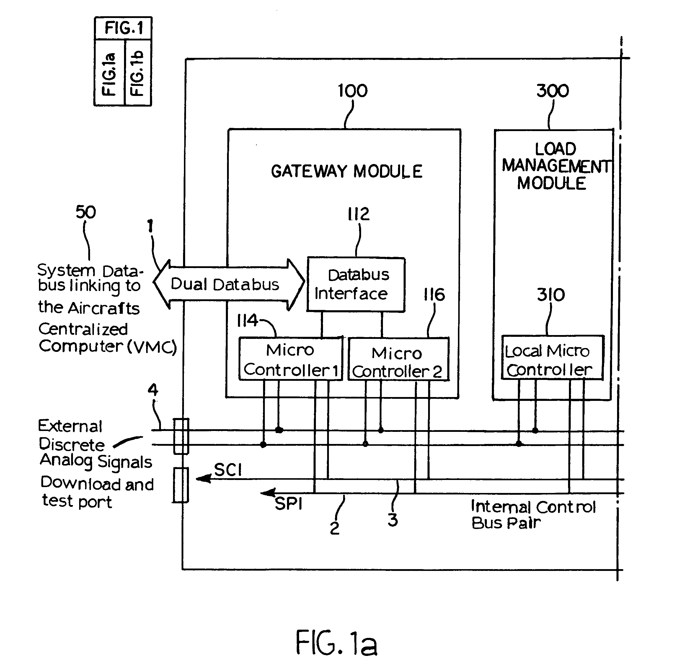
[0010]In accordance with the present invention, the deficiencies in prior systems are overcome by providing an electrical power distribution center comprising: a gateway module including logic to interface to a vehicle management computer (VMC) via a dual redundant standard data bus. The gateway module comprises redundant microcontrollers operably connected to the VMC for selectively controlling the supply of electrical power to a plurality of separate electrical loads. The electrical power distribution center also has two internal serial data buses. The two internal serial data buses are of two different

Problems solved by technology

This shift in technology poses fundamental technical and commercial challenges, which require advanced power distribution controllers such as an Electric Load management Center (ELMC).
However, the Darty et al. design utilizes discrete components to provide limited control of the power switches.
Therefore, this modular solid state power controller with microcomputers is limited to basic on / off control of the power switches and does not permit local control functionality and flexible configuration of the SSPCs.

Method used


Image

  • Electric load management center including gateway module and multiple load management modules for distributing power to multiple loads
  • Electric load management center including gateway module and multiple load management modules for distributing power to multiple loads
  • Electric load management center including gateway module and multiple load management modules for distributing power to multiple loads

Examples


Embodiment Construction

[0018]Aspects of the invention are disclosed in the following description. Those skilled in the art will appreciate that alternate embodiments can be devised without departing from the spirit or the scope of the invention.

[0019]The Electrical Load Management Center (ELMC) is responsible for the distribution of electrical power to the vehicle. It also can supply control logic for some vehicle systems. Thus, the ELMC replaces complex relay logic and circuit cards that are part of the traditional subsystems control. Additionally, the ELMC can provide status information to an electrical power system display to provide a real time picture of the electrical power system configuration.

[0020]By reducing system complexity and increasing system functionality, the ELMC provides lower system weight, higher reliability, higher system availability, better maintainability and lower cost of ownership to the end user.

[0021]As mentioned above, modern vehicles have significantly different electric pow...


PUM


Abstract

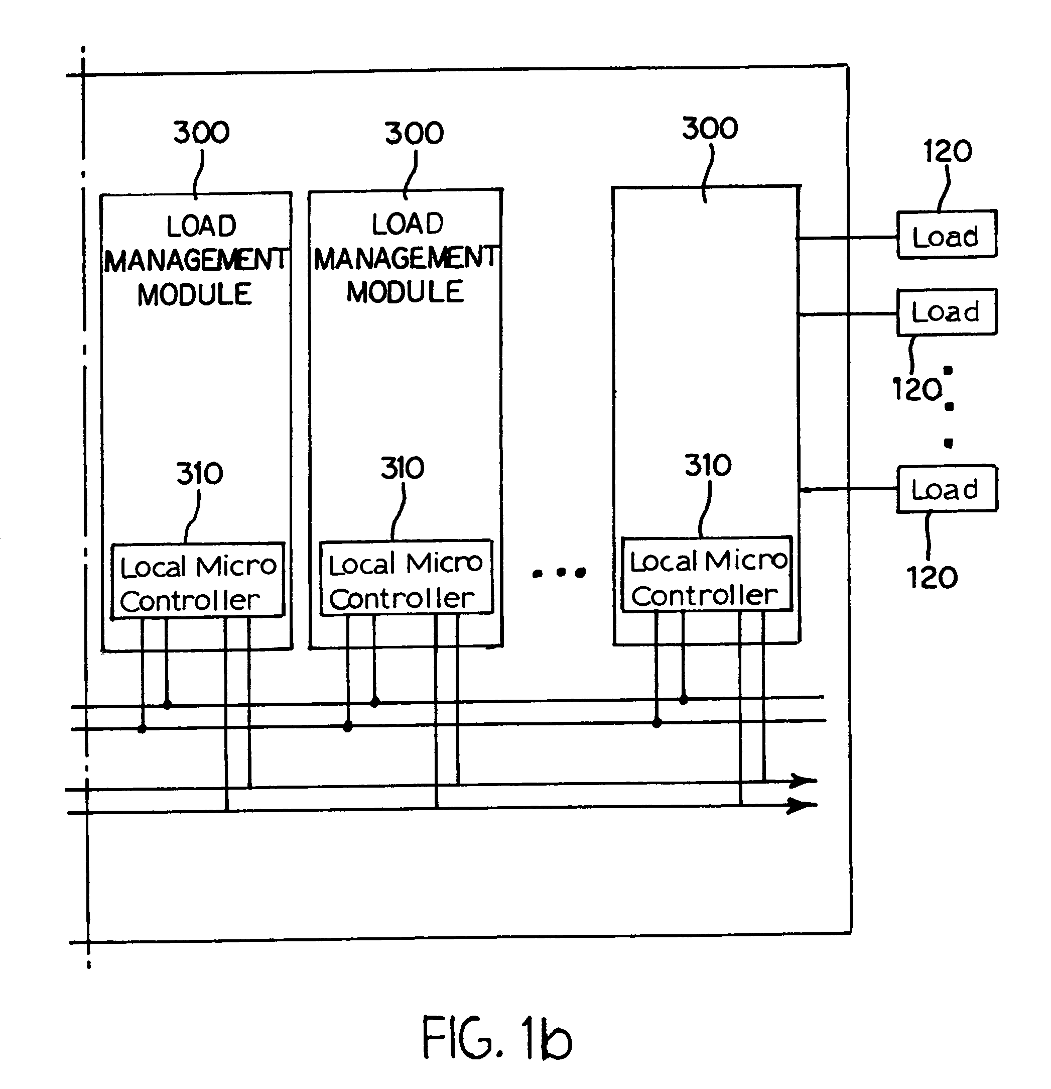
An electrical distribution system is disclosed that includes a gateway module (100) including logic (112) to interface to a vehicle management computer (VMC) (50) via a dual redundant standard data bus (1). The gateway module (100) has redundant microcontrollers (114, 116) operably connected to the VMC (50) for selectively controlling supply of electrical power to a plurality of separate electrical loads (120). The electrical power distribution center also has two internal serial data buses (2,3) that are of two different types. The redundant microcontrollers (114, 116) are each connected to the two internal buses (2,3). A plurality of Load Management Modules (300) is provided. Each are connected to the internal serial data buses (2,3) for receiving control commands via the gateway module (110). Each Load Management Module (300) includes a local microcontroller (310); a plurality of power switching devices (320); and a plurality of application specific integrated circuits (330) corresponding to the plurality of power switching devices (320) for interfacing the power switching devices (320) to the local microcontroller (310).

Description

RELATED APPLICATION[0001]This application claims priority under 35 U.S.C. §119(e) of U.S. Provisional Application No. 60 / 267,520 filed on Feb. 8, 2001, the entire contents of which are herein incorporated by reference.FIELD OF THE INVENTION[0002]The present invention relates to electric power distribution and vehicle power management systems for vehicles having multiple separately controlled electrical loads.BACKGROUND OF THE INVENTION[0003]Electrical power controllers have been used for the distribution of electrical power on aircraft and other vehicles. Additionally, modular approaches to supplying vehicle power have been used to facilitate both maintenance and operability under fault conditions.[0004]New generation vehicles have significantly different electric power requirements. For example, in aerospace systems, there has been a fundamental paradigm shift from predominantly mechanical or electromechanical control to predominantly electronic and computer-based control, with no ...

Claims


Application Information

Patent Timeline
IPC IPC(8): G06F1/26H02J1/00H02J1/10B64D47/00B60R16/02B60R16/03G05D1/00H02H1/00H02H3/00H02H3/05H02H3/093H02J1/14
CPCG05D1/0077G06F1/26H02J1/14B60R16/03H02H3/006H02H3/05H02H3/0935H02H1/0061H02J2310/40H02J2310/44H02J2310/46
Inventor MARES, MIRCEA
Owner HONEYWELL INT INC
Learn More