Redundant packet telecommunication network system using minimum hamming distances to construct a final estimate of a original codeword

a packet telecommunication network and final estimate technology, applied in the field of telecommunications, can solve the problems of unsatisfactory forward error control and automatic repeating, unsatisfactory interruptions in the preferably continuous flow of speech, and ineffective error-correction schemes when packets containing voice data are lost, so as to increase the robustness of the overall effective telecommunication channel and minimize the elapsed time

Inactive Publication Date: 2006-03-28
LUCENT TECH INC +1
View PDF3 Cites 7 Cited by
  • Summary
  • Abstract
  • Description
  • Claims
  • Application Information

AI Technical Summary

Benefits of technology

[0011]The transmitter then transmits a copy of the original codeword onto each of two wireline point-to-point telecommunications channels for delivery to the intended receiver. Advantageously, the two telecommunications channels are both logically and physically distinct. The reason that two copies of the original codeword are transmitted to the receiver via physically distinct channels is to increase the robustness of the overall effective telecommunications channel between the transmitter and the receiver, and to minimize the elapsed time between when the transmitter transmits the original codeword and when receiver has a final estimate of the original codeword available for output.

Problems solved by technology

There exist applications, however, where the prior art techniques of forward error control and automatic-repeat-request are unsatisfactory.
In Internet telephony, the temporal delay associated with automatic-repeat-request causes unsatisfactory interruptions in the preferably continuous flow of speech.
Although this problem can generally be avoided by using error-correction coding schemes, error-correction schemes are ineffective when packets containing voice data are lost or delayed during transmission.

Method used


Image

  • Redundant packet telecommunication network system using minimum hamming distances to construct a final estimate of a original codeword
  • Redundant packet telecommunication network system using minimum hamming distances to construct a final estimate of a original codeword
  • Redundant packet telecommunication network system using minimum hamming distances to construct a final estimate of a original codeword

Examples


Embodiment Construction

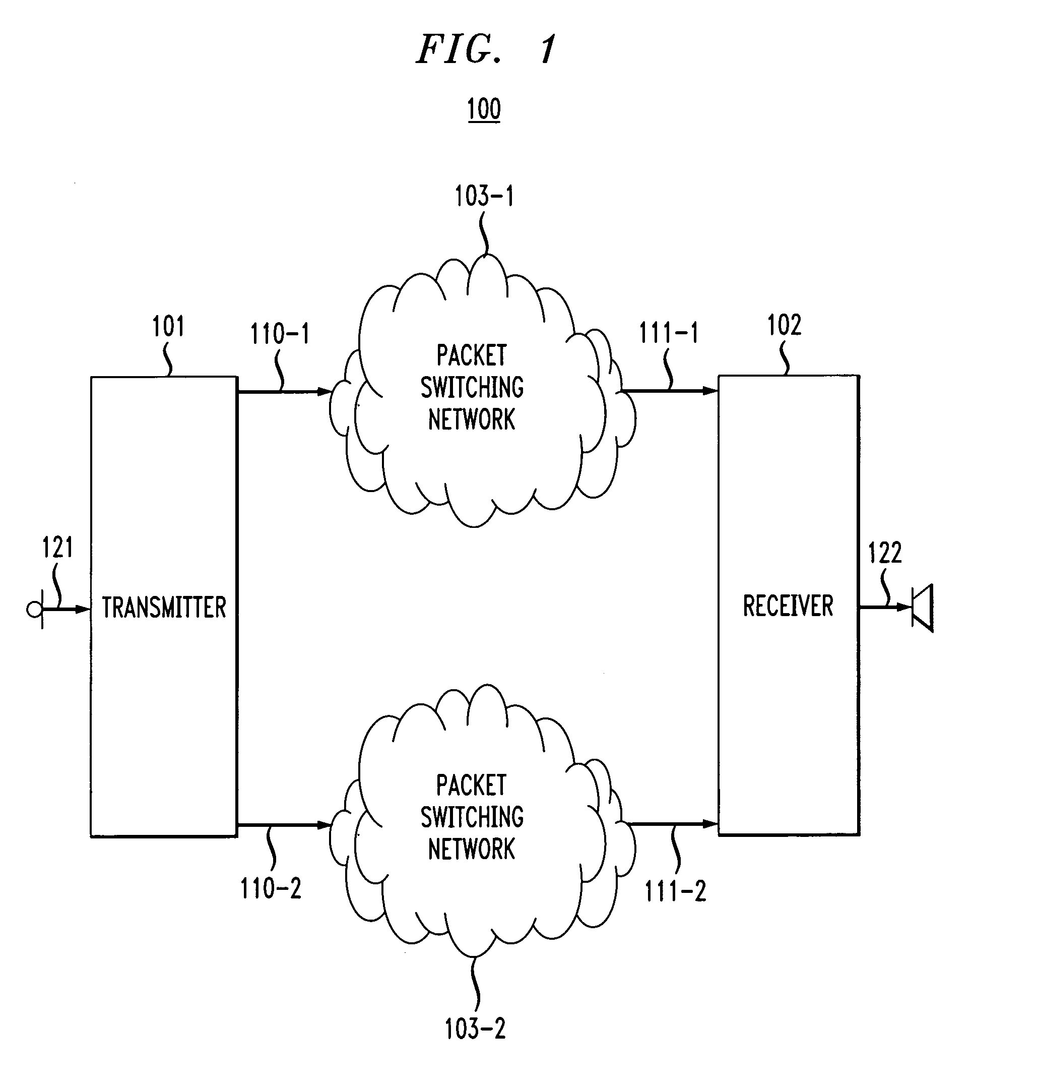
[0019]FIG. 1 depicts a schematic diagram of redundant packet network 100 in accordance with the illustrative embodiment of the present invention. Redundant packet network 100 comprises: transmitter 101 and receiver 102 connected by two logically and physically distinct point-to-point telecommunications channels. The first point-to-point telecommunications channel (hereinafter also called the “A-channel”) comprises: physical telecommunications path 110-1, packet switching network 103-1, and physical telecommunications path 111-1. The second point-to-point telecommunications channel (hereinafter also called the “B-channel”) comprises: physical telecommunications path 110-2, packet switching network 103-2, and physical telecommunications path 111-2. The input to transmitter 101 is microphone 121, and the output from receiver 102 is speaker 122.

[0020]In accordance with the illustrative embodiment of the present invention, each of the first point-to-point telecommunications channel and t...


PUM


Abstract

A method of forward error control in which a transmitter receives data from an input device and creates one or more original codewords that are transmitted onto each of two physically distinct telecommunications channels. Two copies of the original codeword are transmitted to the receiver via physically distinct channels to increase the robustness of the telecommunications channel between the transmitter and the receiver and to minimize the elapsed time between when the transmitter transmits the original codeword and when receiver has a final estimate of the original codeword available for output.

Description

CROSS-REFERENCE TO RELATED APPLICATIONS[0001]This application is related to U.S. Publication No. 2002 / 0162071, now abandoned, filed Feb. 22, 2001 and entitled “Forward-Error Control of Redundantly-Transmitted Codewords” (Attorney Docket S.J. Chang 12), which application is incorporated by reference.FIELD OF THE INVENTION[0002]The present invention relates to telecommunications in general, and, more particularly, to forward error control in packet networks.BACKGROUND OF THE INVENTION[0003]The problem of dealing with transmission errors in telecommunications networks has been studied for many years. In general, the solutions for dealing with transmission errors fall into two classes: (i) forward error control, and (ii) automatic-repeat-request.[0004]In accordance with forward error control, data is encoded in accordance with an error-control coding scheme that increases the likelihood that the receiver can detect and correct any errors that might occur during transmission.[0005]In acc...

Claims


Application Information

Patent Timeline
Patent Type & Authority Patents(United States)
IPC IPC(8): G06F11/00H04L1/08H04L1/22H04L69/40
CPCH04L1/08H04L1/22H04L69/40H04L29/06H04L69/14H04L9/40
Inventor CHANG, SHIH-JEH
Owner LUCENT TECH INC
Why Eureka
Try Eureka