Engine exhaust particulate after-treatment system

a technology of aftertreatment system and engine exhaust, which is applied in the direction of machines/engines, mechanical equipment, electrical control, etc., can solve the problems of deteriorating durability, not approaching the problem of dissolution loss of particulate filters, and increasing the temperature of particulate filters. to achieve the effect of suppressing the temperature ris

Inactive Publication Date: 2006-04-04
MAZDA MOTOR CORP
View PDF10 Cites 46 Cited by
  • Summary
  • Abstract
  • Description
  • Claims
  • Application Information

AI Technical Summary

Benefits of technology

[0011]An object of the present invention is to provide an engine exhaust particulate after-treatment system that can suppress the temperature rise of a particulate filter on engine deceleration during the removal of exhaust particulates.

Problems solved by technology

In the above known technique, however, if the engine operating condition changes to a deceleration condition in the course of regeneration of the particulate filter, this may cause a problem that the temperature of the particulate filter may rise suddenly to deteriorate the durability thereof.
This known art technique, however, does not approach the problem of dissolution loss of the particulate filter until the engine operating mode has shifted from a high load to idling condition and the temperature of the particulate filter increases, and does not intend to prevent the occurrence of temperature rise of the particulate filter on engine deceleration which means the period of transition from a high load to idling condition.
Therefore, the above problem cannot be solved by this known art technique, nor has it still been solved.

Method used


Image

  • Engine exhaust particulate after-treatment system
  • Engine exhaust particulate after-treatment system
  • Engine exhaust particulate after-treatment system

Examples


embodiment 1

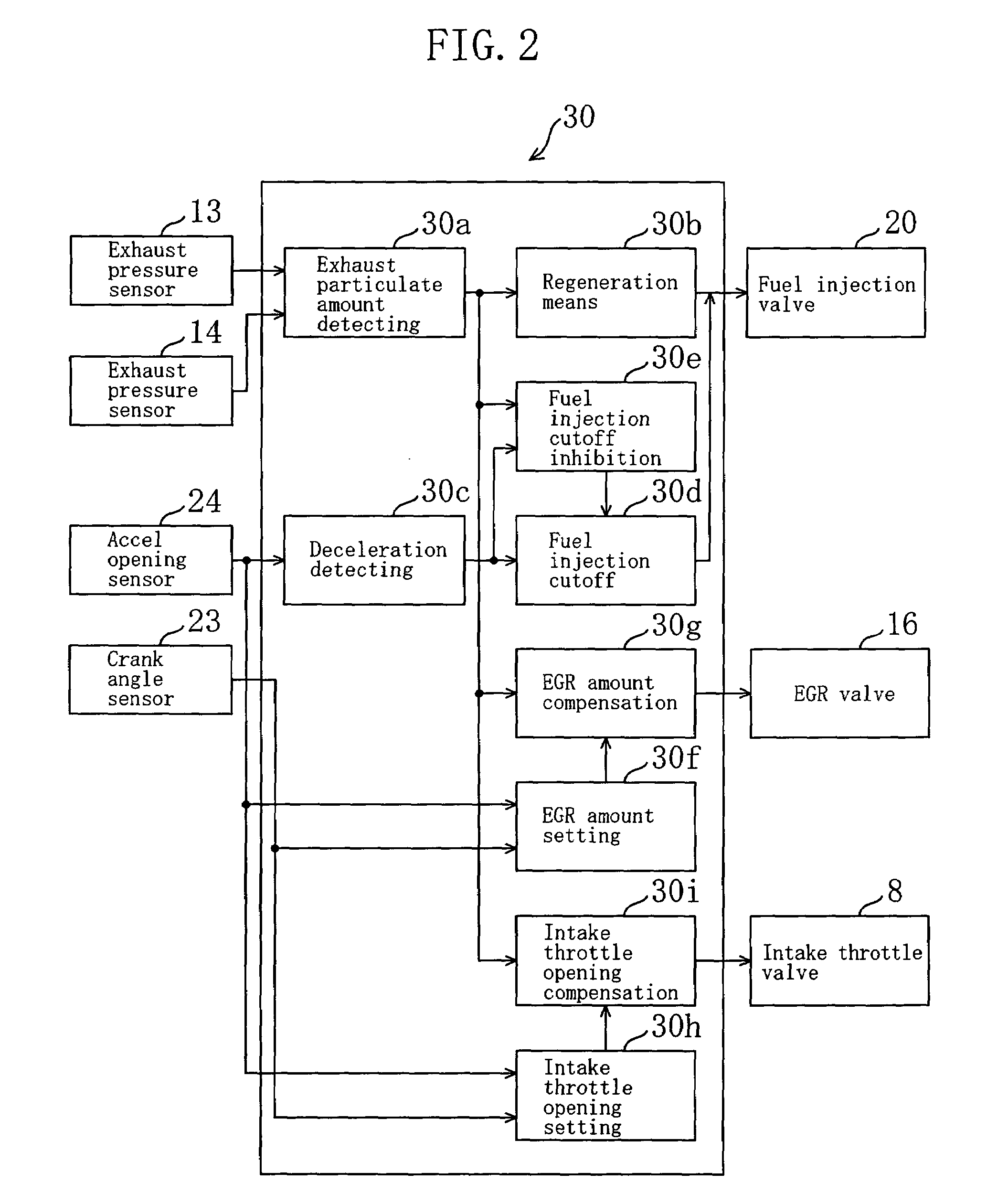
[0082]FIG. 2 is a control block diagram in Embodiment 1, and shows a case of restricting, when the engine operating condition changes to a deceleration condition during the removal by burning of exhaust particulates, the drop of the flow rate of exhaust gases flowing into the particulate filter 12. The controls in this case include: (a) compensating for the amount of recirculation of exhaust gases (EGR amount) subtractively; (b) compensating for the opening angle of the intake throttle valve 8 to become wider; and (c) inhibiting fuel injection cutoff during deceleration.

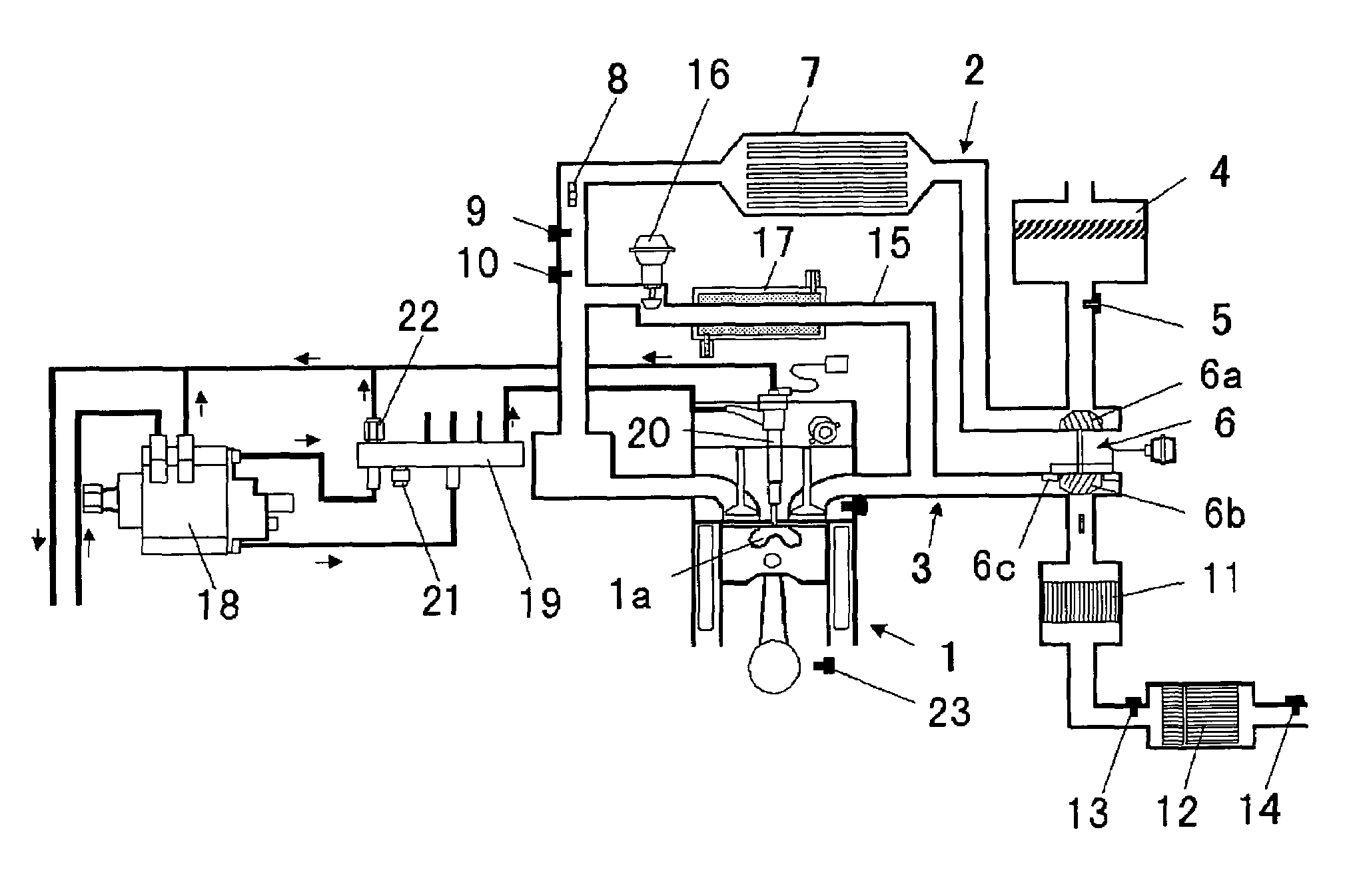
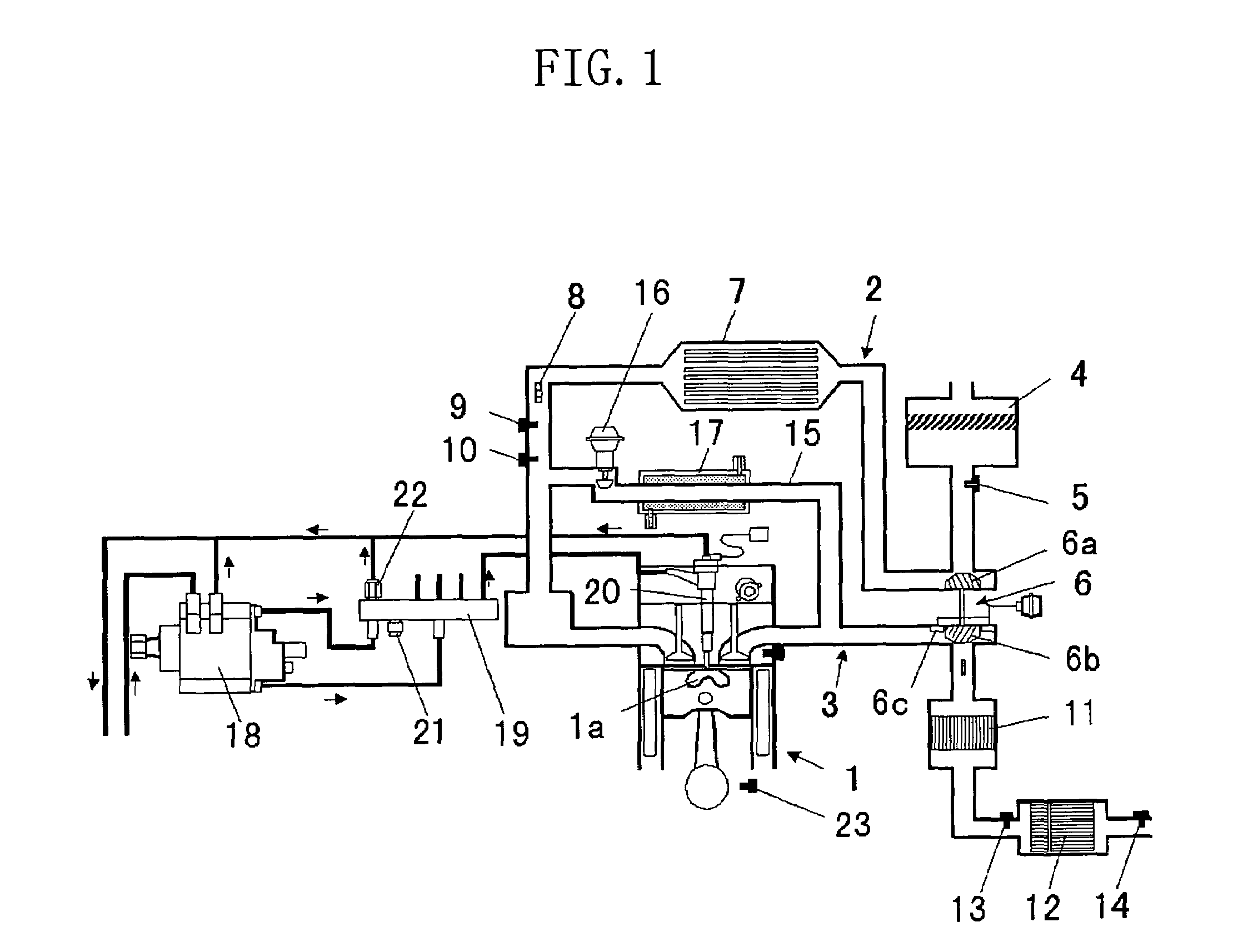
[0083]Detection signals from the exhaust pressure sensors 13 and 14, the crank angle sensor 23 and an accel opening sensor 24 are input to an engine control unit 30 for controlling the intake throttle valve 8, the EGR valve 16 and the fuel injection valve 20.

[0084]First, description will be made about fuel injection control.

[0085]The engine control unit 30 is provided with an exhaust particulate amount detecting mean...

embodiment 2

[0118]Next, description will be made about Embodiment 2 of the present invention.

[0119]The phenomenon that the temperature of the particulate filter 12 rises on engine deceleration during the removal by burning of exhaust particulates equally arises not only on engine deceleration during a forced regeneration as described in Embodiment 1 but also on engine deceleration during a natural regeneration which is in the operating zone outside of the preset curve L1 referred to in the description of FIG. 3 and in which the engine speed and load are high and the exhaust gas temperature is originally high.

[0120]Embodiment 2 is the case of restricting, on engine deceleration during a natural regeneration, the drop of the flow rate of exhaust gases flowing into the particulate filter 12. The specific measures for restricting the drop of the flow rate of exhaust gases includes, like Embodiment 1, (a) compensating for the amount of recirculation of exhaust gases (EGR amount) subtractively, (b) c...

embodiment 3

[0128]Next, description will be made about Embodiment 3 of the present invention.

[0129]Embodiment 3 is the case that when the engine enters a deceleration condition under the condition in which exhaust particulates are removed by burning, the shift lines for changing the gear ratio of an automatic transmission are compensated for to a higher vehicle speed side to increase the engine speed and in turn increase the amount of air taken into the engine, or to restrict the drop of the engine speed, resulting in restricting the drop of the flow rate of exhaust gases flowing into the particulate filter 12.

[0130]FIG. 7 is a control block diagram of Embodiment 3. As shown in the figure, the engine control unit 30 is provided, like Embodiments 1 and 2, with an exhaust particulate amount detecting means 30a and regeneration means 30b in order to control the fuel injection valve 20 to remove exhaust particulates by burning.

[0131]The exhaust particulate after-treatment system of this embodiment ...


PUM


Abstract

An exhaust particulate trapping means 12 for trapping particulates in exhaust gases is provided in an exhaust path 3 of an engine. When the engine enters a deceleration condition during the removal by burning of exhaust particulates trapped by the exhaust particulate trapping means 12, the drop of the flow rate of exhaust gases flowing into the exhaust particulate trapping means 12 is restricted. Thus, the cooling action of the exhaust particulate trapping means 12 through heat exchange with the exhaust gases can be kept up to suppress that the temperature of the exhaust particulate trapping means 12 excessively rises on engine deceleration.

Description

BACKGROUND OF THE INVENTION[0001](a) Field of the Invention[0002]This invention relates to an engine exhaust particulate after-treatment system.[0003](b) Description of the Related Art[0004]For the purpose of purification of exhaust gases from diesel engines, there has been recently employed a technology for trapping exhaust particulates such as carbon contained in exhaust gases by a particulate filter disposed in an exhaust path of the engine to prevent atmospheric release.[0005]In such a diesel engine provided with a particulate filter, when the amount of exhaust particulate accumulated on the particulate filter reaches a saturation amount which is the limit to which the particulate filter can accumulate exhaust particulates, it is necessary to burn the accumulated exhaust particulates to regenerate the function of the filter.[0006]As an example of filter regeneration techniques, there is known one for burning exhaust particulates in such a manner to raise the exhaust gas temperat...

Claims


Application Information

Patent Timeline
Patent Type & Authority Patents(United States)
IPC IPC(8): F01N3/00B60W10/04B60W10/02B60W10/06B60W10/10B60W10/103B60W10/11F01N3/02F01N3/023F01N3/025F01N3/029F01N3/035F01N9/00F01N13/02F02B3/06F02B29/04F02B37/00F02D9/02F02D21/08F02D29/00F02D41/00F02D41/02F02D41/04F02D41/12F02D45/00F02M25/07F16H61/00F16H61/02F16H61/48F16H63/50
CPCF01N3/023F01N13/009F01N9/002F02B37/00F02D41/0005F02D41/005F02D41/0225F02D41/029F02D41/045F02D41/123F02M25/0731F02M25/0754F02M25/0755F01N3/035F02B3/06F02B29/0406F02D2041/0022F02M25/0707F02M25/0738F16H61/0213Y02T10/144Y02T10/42Y02T10/47F02M26/46F02M26/05F02M26/28F02M26/33F02M26/47Y02T10/12Y02T10/40
Inventor NISHIMURA, HIROYUKIYASHIKI, ERIKO
Owner MAZDA MOTOR CORP
Why Eureka
Try Eureka