
Device to absorb the axial loads generated on the rolls in a rolling stand

Inactive Publication Date: 2006-04-04
DANIELI & C OFF MEC SPA
View PDF11 Cites 6 Cited by
  • Summary
  • Abstract
  • Description
  • Claims
  • Application Information

AI Technical Summary

Benefits of technology

[0013]One purpose of the invention is to achieve a device which will allow both the working rolls and the back-up rolls to be contained axially so that the vertical force generated by friction can be restrained to very low levels, to limit as much as possible the hysteresis which impedes the small vertical movements of the roll pack during rolling, which are needed to adequately control the thickness.

Problems solved by technology

Thus a hysteresis is created which has a harmful effect on the correct control of the thickness of the rolled product.

Method used


Image

  • Device to absorb the axial loads generated on the rolls in a rolling stand
  • Device to absorb the axial loads generated on the rolls in a rolling stand
  • Device to absorb the axial loads generated on the rolls in a rolling stand

Examples


Embodiment Construction

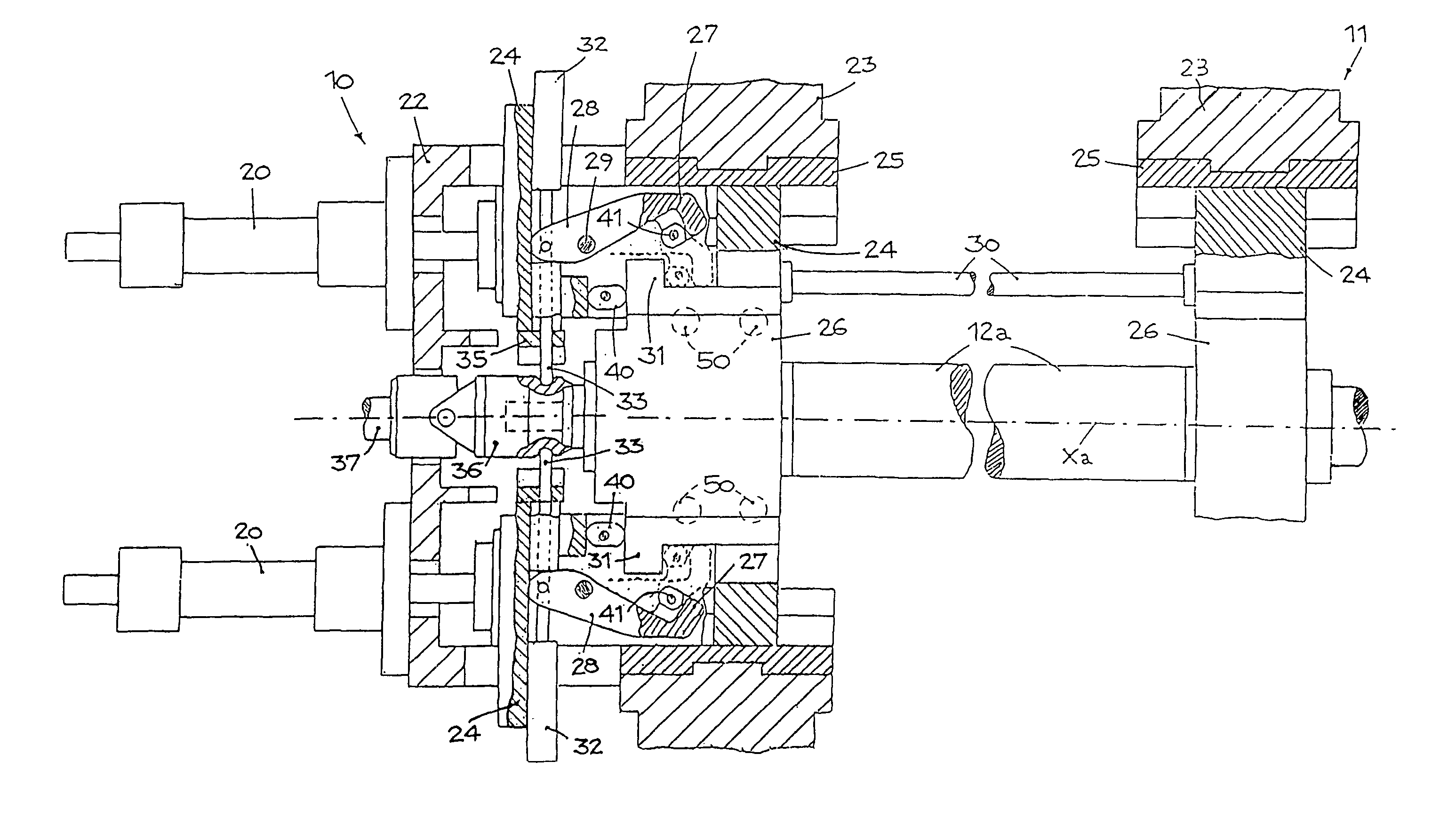
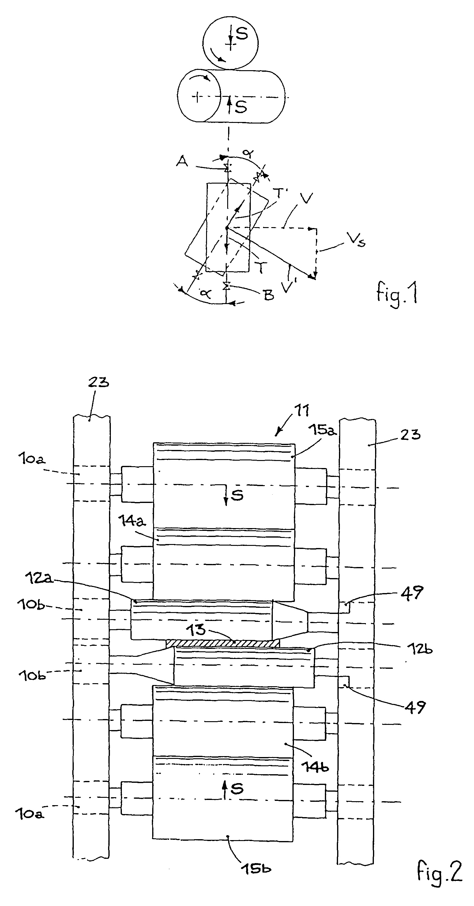
[0023]With reference to FIG. 2, a device 10a–10b according to the invention is shown assembled in a six-high rolling stand 11, which comprises a pair of working rolls 12a, 12b, between which the plane product 13 to be rolled, consisting for example of steel strip, is able to pass.

[0024]Associated with the two working rolls 12a, 12b there are two corresponding intermediate rolls 14a, 14b, and two back-up rolls 15a, 15b which are able to contrast the thrusts due to the rolling of the product 13 and to prevent an excessive bending of the working rolls 12a, 12b and that of the intermediate rolls 14a, 14b.

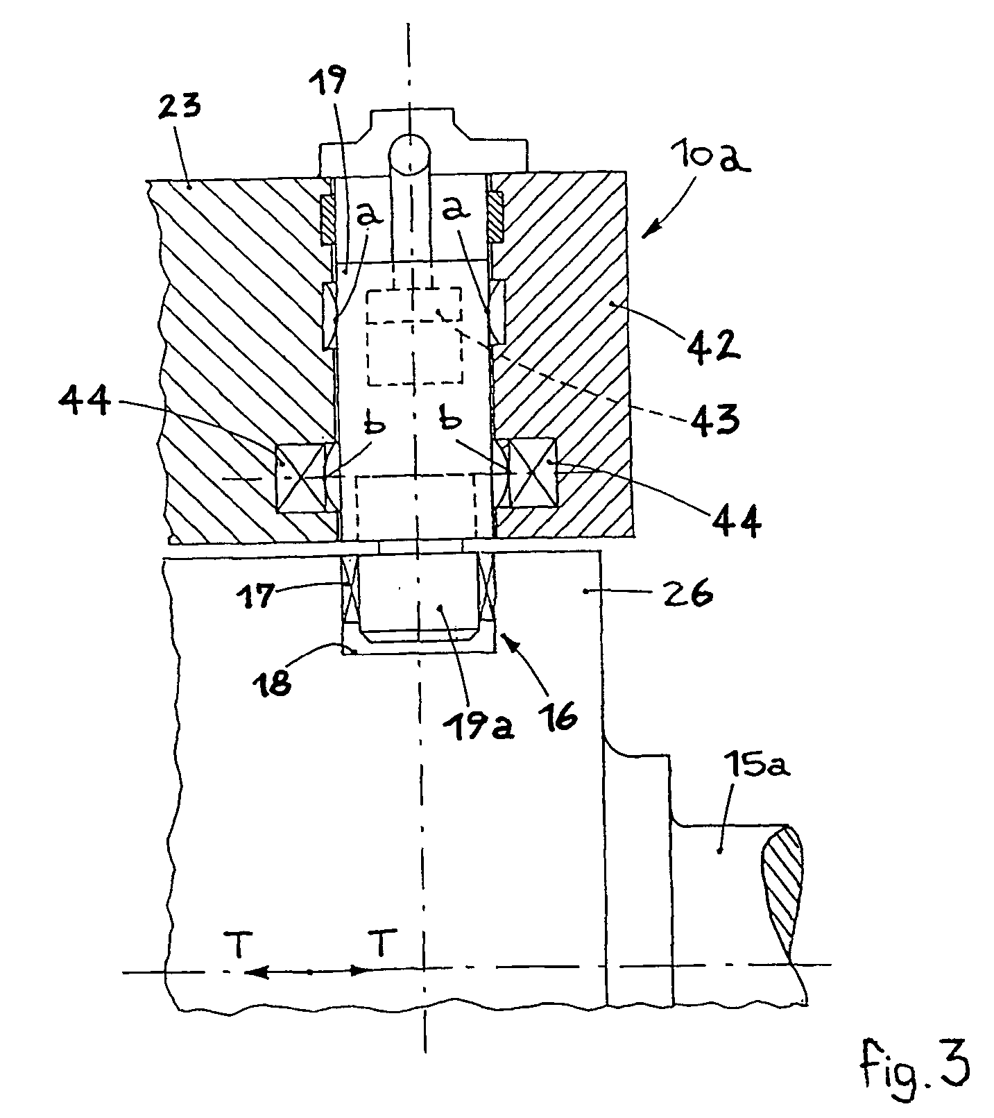
[0025]The device according to the invention comprises two assemblies 10a associated with the back-up rolls 15a and 15b and two assemblies 10b associated with the working rolls 12a and 12b, to support them adequately with respect to the housings 23 of the stand 11.

[0026]Each device 10a (FIG. 3) associated with the back-up rolls 15a and 15b comprises a holding element 16 provided with a ...


PUM

PropertyMeasurementUnit
Timeaaaaaaaaaa
Forceaaaaaaaaaa
Elasticityaaaaaaaaaa

Abstract

Device to absorb the axial loads generated on the rolls in a rolling stand (11) having a pair of working rolls (12a, 12b), a corresponding pair of back-up rolls (15a, 15b) and at least an intermediate roll (14) located between a working roll (12a) and a corresponding back-up roll (15a), in said device holding means (16, 40, 41) are provided to support the axial loads on the back-up rolls (15a, 15b) and / or the working rolls (12a, 12b) caused by the crossing of said at least one intermediate roll (14), so that the axial loads are discharged onto elements with very low rolling friction, totally or almost totally annulling the hysteresis relating to the vertical movements of the back-up rolls (15a, 15b) and working rolls (12a, 12b) and the relative chocks (26).

Description

FIELD OF THE INVENTION[0001]The invention refers to a device to absorb the axial loads generated on the rolls in a rolling stand, and in particular on the working rolls and the back-up rolls in a six-high stand.BACKGROUND OF THE INVENTION[0002]It is well-known that two counter-rotating rolls thrust against each with a determined force S and subjected to reciprocal crossing by a determined angle α (FIG. 1), even limited to a few tenths of a degree, with respect to the vertical plane passing through the median rolling axis, are also subject to axial thrusts.[0003]In the zone of contact between the working rolls in a rolling stand, because of the sliding speeds VS=V′−V (vectorial difference of the peripheral speeds of the rolls), where V is the peripheral speed of the upper roll and V′ is the peripheral speed of the lower roll, and because of the contact friction due to the force S, axial forces T are produced on the upper roll and T′ on the lower roll, which can even be of strong inte...

Claims


Application Information

Patent Timeline
IPC IPC(8): B21B31/02B21B13/02B21B31/18
CPCB21B13/023B21B31/185B21B2013/028B21B2013/026
Inventor DRIGANI, FAUSTOPAWLOWSKI, STANISLAWVENTULINI, ENRICO
Owner DANIELI & C OFF MEC SPA
Learn More