Combustion type power tool having avoiding unit for avoiding overheating to mechanical components in the tool

a technology of mechanical components and power tools, which is applied in the direction of manufacturing tools, nailing tools, machines/engines, etc., can solve the problems of prolonging the service life of batteries for saving costs, and achieve the effects of reducing working efficiency, avoiding temperature increase of tools, and improving working efficiency and operability

Inactive Publication Date: 2006-04-04
HITACHI KOKI CO LTD
View PDF8 Cites 38 Cited by
  • Summary
  • Abstract
  • Description
  • Claims
  • Application Information

AI Technical Summary

Benefits of technology

[0016]Alternatively, the temperature detecting unit is disposed at the cylinder. Since the temperature detection unit is disposed at the cylinder, control is performed based on the temperature of the cylinder. Thus, the predetermined temperature is determined in view of eliminations of overheating and thermal deformation of the cylinder. Therefore, lowering of working efficiency due to overheating and the deformation can be prevented.
[0017]Alternatively, one of the components in the housing includes an exhaust cover covering the exhaust check valve for changing a exhausting direction into an axial direction of the housing, the temperature detecting unit being disposed at the exhaust cover. Since the temperature detection unit is disposed at the exhaust cover, control is performed based on the temperature of the exhaust cover. The exhaust cover is directly exposed to the exhaust gas and becomes to have the highest temperature among components in the power tool. The control is performed based on the temperature of the exhaust cover, i.e., based on the temperature of the highest temperature component in the tool. Since temperature of the remaining components is lower than that of the exhaust cover, further temperature increase of the tool can be avoided, thereby improving working efficiency and operability.
[0018]Alternatively, the temperature detecting unit is disposed at a wall of the housing. Since the temperature detection unit is disposed at the wall of the housing, control is performed based on the temperature of the housing. Thus, the predetermined temperature is determined in view of eliminations of softening and distortion of the housing. Therefore, lowering of working efficiency due to the deformation can be prevented.
[0019]The combustion-type power tool further includes alarm means disposed at one of the housing and the handle for alarming that the temperature detected by the temperature detecting unit exceeds the predetermined temperature. Therefore, the user of the tool can provisionally recognize that the driving operation should not be performed. If the alarm is ended, the user can recognize the re-start of operation, thereby improving working efficiency and operability.
[0020]Preferably, the cooling control unit includes a fan rotation continuing unit that continues rotation of the fan until the temperature detected by the detecting unit becomes not more than the predetermined temperature. Since the cooling control unit continues rotation of the fan until the detected temperature becomes not more than the predetermined temperature, the cylinder and the combustion chamber frame can be rapidly cooled.
[0021]Alternatively, the cooling control unit includes a fan rotation speed controller that controls rotation speed of the fan to a first rotation speed when the temperature detected by the detecting unit is not more than the predetermined temperature, and to a second rotation speed higher than the first rotation speed when the temperature detected by the detecting unit exceeds the predetermined temperature. The fan rotation speed controller maintains the second rotation speed until the temperature detected by the detecting unit becomes not more than the predetermined temperature. Therefore, the cylinder and the combustion chamber frame can be rapidly cooled.

Problems solved by technology

Further, since the cooling control unit controls rotation of the fan only when immediate cooling is required, service life of the battery can be prolonged for saving cost in comparison with a case where the fan is always rotated so that the tool does not reach the abnormal temperature.

Method used


Image

  • Combustion type power tool having avoiding unit for avoiding overheating to mechanical components in the tool
  • Combustion type power tool having avoiding unit for avoiding overheating to mechanical components in the tool
  • Combustion type power tool having avoiding unit for avoiding overheating to mechanical components in the tool

Examples


first embodiment

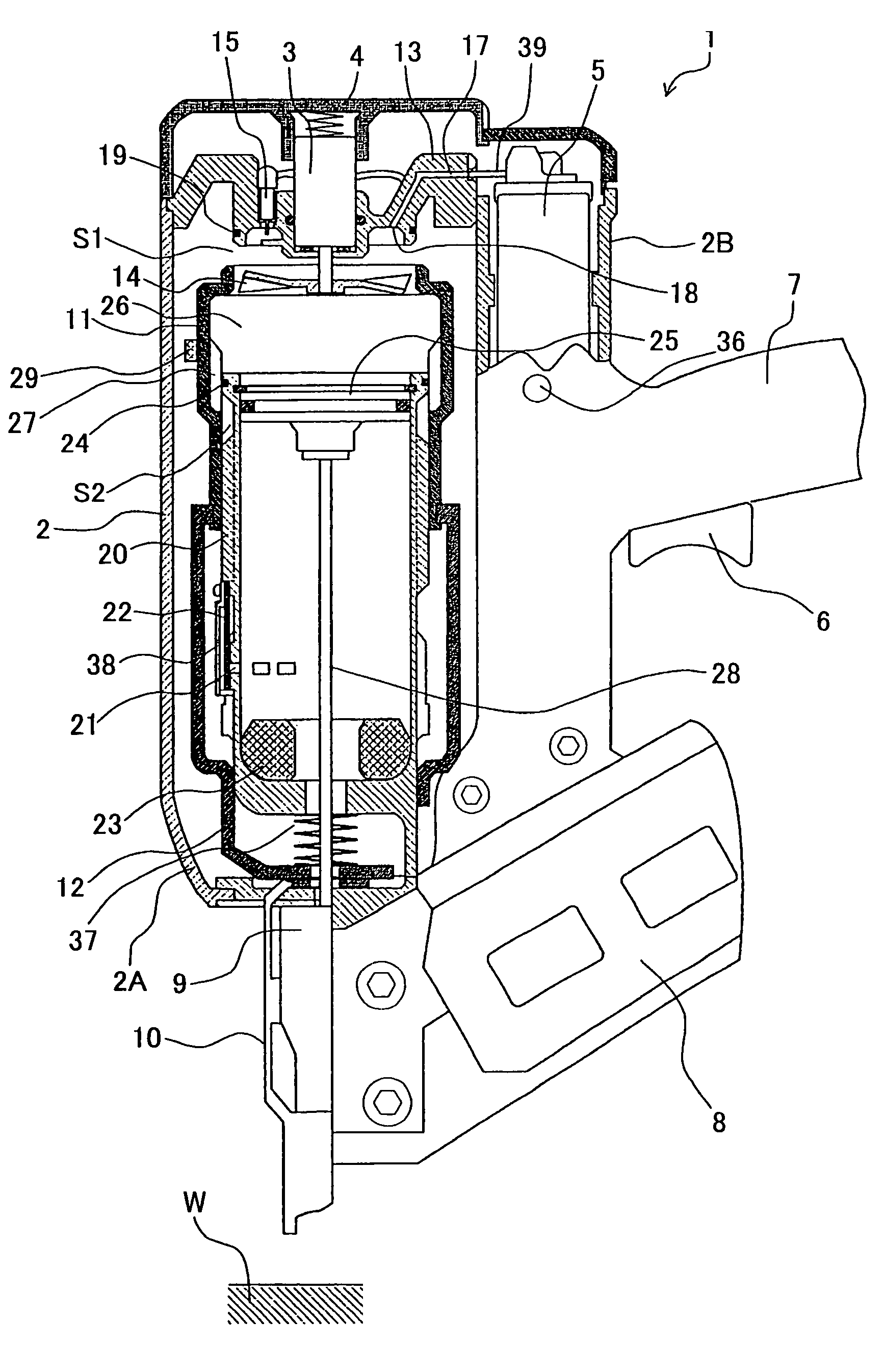
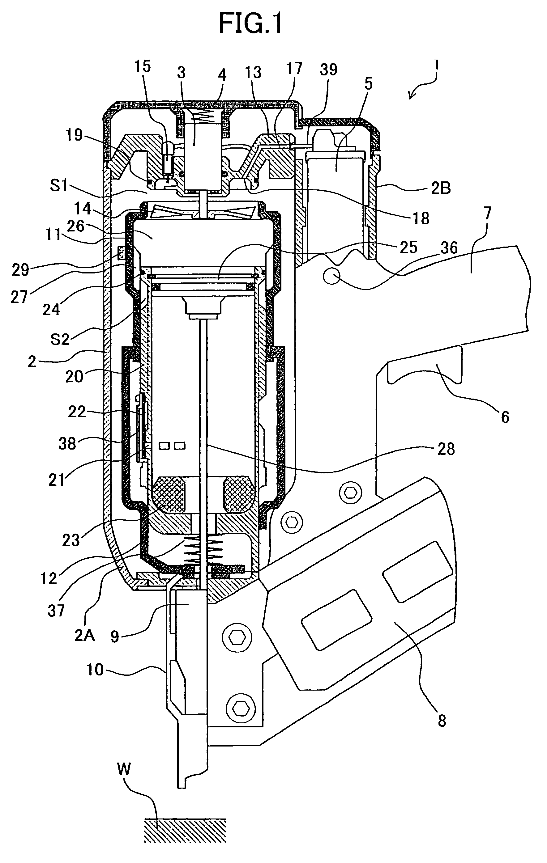
[0035]A combustion-type power tool according to the present invention will be described with reference to FIGS. 1 through 3(b). The embodiment pertains to a combustion type nail driver. The combustion type nail driver 1 has a housing 2 constituting an outer frame and including a main housing 2A and a canister housing 2B juxtaposed to the main housing 2A. The main housing 2A has a top portion provided with a head cover 4 in which an intake port is formed, and has a bottom portion formed with an exhaust port (not shown).

[0036]A gas canister 5 containing therein a combustible gas is detachably disposed in the canister housing 2B. A handle 7 having a trigger switch 6 extends from the canister housing 2B. The handle 7 houses therein a battery for driving a motor 3 and an ignition plug 15 described later. A magazine 8 and a tail cover 9 are provided on the bottoms of the main housing 2A and canister housing 2B. The magazine 8 contains nails (not shown), and the tail cover 9 is adapted to ...

fifth embodiment

[0075]FIG. 8 shows a block circuit executing driving and non-driving to the fan 14 and ignition or non-ignition to the ignition plug 15 in the A first OR circuit 441 has two input terminals one being connected to the trigger switch 6 and the other being connected to the head switch 16. The first OR circuit 441 has an output terminal connected to a first input terminal of a second OR circuit 442. The second OR circuit 442 has an output terminal connected to a fan driver circuit 443 connected to the fan 14. Therefore, the operation of the fan driver circuit 443 starts for starting rotation of the motor 3 thereby starting rotation of the fan 14 in response to ON operation of at least one of the trigger switch 6 and the head switch 16.

[0076]A fan timer 444 is connected between the output terminal of the first OR circuit 441 and a second input terminal of the second OR circuit 442. The fan timer 444 starts to provide H level state when the trigger switch 6 and the head switch 16 are tur...


PUM


Abstract

A combustion type power tool capable of avoiding damage to seal members and a housing to prolong a service life, and capable of enhancing operability and workability. Temperature elevation of a combustion chamber frame due to combustion of a mixture of combustible gas and air is detected by a temperature sensor disposed in a housing. If the detected temperature exceeds a preset temperature, ignition of an ignition plug is prohibited by a prohibiting unit in spite of ON operation of a trigger switch. In this state, alarming is performed by a display to notify the user of the inoperable state of the tool. Similar control can be made when the temperature sensor is disposed at a cylinder, an exhaust cover and the housing.

Description

BACKGROUND OF THE INVENTION[0001]The present invention relates to a combustion-type power tool, and more particularly, to a combustion-type fastener driving tool in which liquidized gas is ejected from a gas canister into a combustion chamber, mixed with air and ignited to drive a piston, thus generating power to drive nails or the like.[0002]A conventional combustion-type driving tool generally includes a housing, a handle, a trigger switch, a head cap, a combustion-chamber frame, a push lever, a cylinder, a piston, a driver blade, a motor, a fan, a gas canister, an ignition plug, an exhaust-gas check valve, an exhaust cover, a magazine, and a tail cover. The head cap closes one end of the housing and is formed with a combustible gas passage. The handle is fixed to the housing and is provided with the trigger switch. The combustion-chamber frame is movable in the housing in the lengthwise direction thereof. The combustion-chamber frame is urged in a direction away from the head cap...

Claims


Application Information

Patent Timeline
Patent Type & Authority Patents(United States)
IPC IPC(8): F02B71/00B25C1/08
CPCB25C1/08
Inventor OHMORI, YASUKISASAKI, YASUOFUJISAWA, HARUHISA
Owner HITACHI KOKI CO LTD
Why Eureka
Try Eureka