Device and method for tacking a prosthetic screen

a prosthetic screen and device technology, applied in the field of devices and methods for tacking prosthetic screens, can solve the problems of high failure rate of repair, visible bulge, infection and death if not surgically repaired, etc., and achieve the effect of not producing as much postoperative pain, excellent handling, and easy grasping

Inactive Publication Date: 2006-04-04
TOOLS FOR SURGERY
View PDF16 Cites 192 Cited by
  • Summary
  • Abstract
  • Description
  • Claims
  • Application Information

AI Technical Summary

Problems solved by technology

If there is a defect in the fascia, abdominal contents may penetrate weaker layers of the abdominal wall (comprised of muscle or fat) and push ahead the abdominal cavity's thin lining (peritoneum) so that abdominal contents, such as omentum or bowel, within their envelope of peritoneum, become situated in a subcutaneous position, often causing a visible bulge.
Viscera being squeezed through a fascia defect can cause pain.
This may lead to infection and death if not surgically repaired.
This is relatively easy to do, but the repair has a high rate of failure because the sutured prosthesis often pulls away from the fascial edge.
However materials such as Gortex™ or polypropylene mesh used for prosthetic screens are soft and may buckle and deform outside the suture line, so that the structural advantage of the overlap with fascia is not realized.
However, it can be difficult to secure an overlapping intraperitoneal prosthesis at its periphery when performing surgery using a conventional approach.
Access to the inside surface of the abdominal wall overlying the periphery of the prosthesis is limited.
The more the overlap, the more difficult the access.
Despite the many advances made in laparoscopic suturing techniques as well as in open hernia repair, there are still many problems to be overcome.
One problem is that in order to secure the prosthesis to the abdominal wall at a single point with a transmural suture, each suture end must be pulled separately through the abdominal wall.
This is time consuming.
Another problem is that after placement of both ends of each suture through the abdominal wall, they must be clamped together above the body wall while other transmural sutures are placed, because it is much easier to place transmural sutures before the prosthesis is hoisted up against the abdominal wall.
A large number of clamps clutter the operative field and the sutures and clamps tend to entangle one another.
This process is somewhat time consuming and the multiple skin incisions produce a poor cosmetic result.
This often produces postoperative pain and cosmetically undesirable dimpling of the skin at the ligature sites.

Method used


Image

  • Device and method for tacking a prosthetic screen
  • Device and method for tacking a prosthetic screen
  • Device and method for tacking a prosthetic screen

Examples


Embodiment Construction

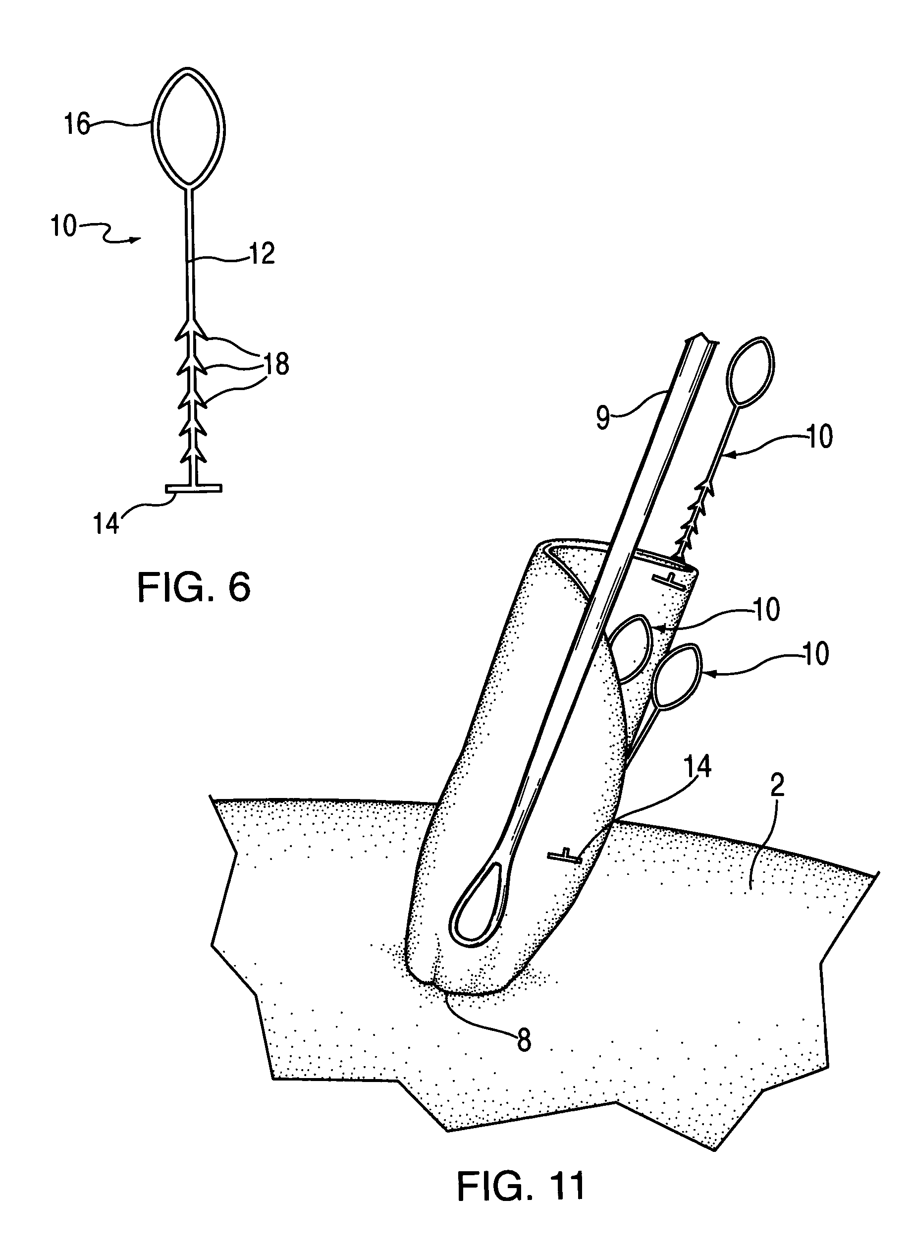
[0039]Turning now to FIG. 6, a prosthetic screen tacking device 10 includes a filament 12 with a perpendicular foot 14 at one end and a loop 16 at the other end. A plurality of barbs 18 are provided adjacent to the foot 14. The foot 14 may be a linear form, so that end of the device forms a T or may have other configurations as described in more detail below with reference to FIGS. 13–15. The barbs 18 are angulated in such a manner that they permit movement of the device through tissue in one direction (toward the loop 16), but prevent movement in the opposite direction (toward the foot 14).

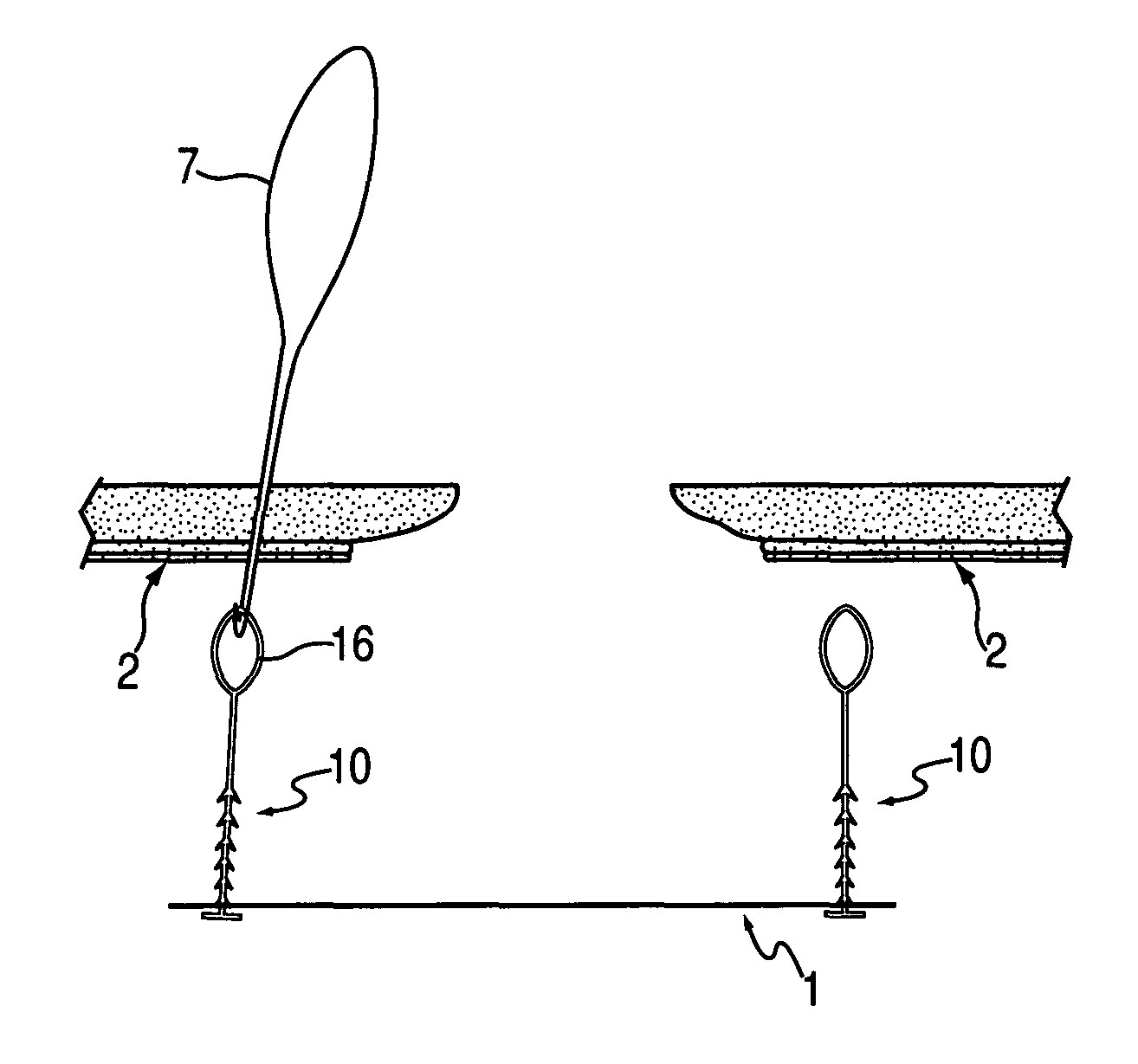
[0040]FIGS. 7–10 illustrate how the tacking device 10 is used in the open method of hernia repair. Several devices 10 are pulled through the prosthetic screen 1 equidistantly along the periphery (circumference) of the prosthesis 1. The assembly is then positioned within the open peritoneal cavity, over the viscera (FIG. 7). A suture passer 7 (e.g. a Reverdin needle) is then used to penetrate the ...


PUM


Abstract

A prosthetic screen tacking device includes a barbed filament with a perpendicular foot at one end and a loop at the other. The barbs are situated near the foot and angulated in such a manner that they permit movement of the device through tissue in one direction (toward the loop), but prevent movement in the opposite direction (toward the foot). Different barbs and feet are shown. Methods of using the device with or without an associated button are also disclosed.

Description

BACKGROUND OF THE INVENTION[0001]1. Field of the Invention[0002]The invention relates to a device and method which simplifies the attachment of a prosthetic screen to the abdominal wall during the repair of abdominal wall hernias.[0003]2. Brief Description of the Prior Art[0004]The layer or layers of fascia which lie in the abdominal wall and surround the peritoneal cavity are the strong structures which maintain the integrity of the peritoneal cavity. If there is a defect in the fascia, abdominal contents may penetrate weaker layers of the abdominal wall (comprised of muscle or fat) and push ahead the abdominal cavity's thin lining (peritoneum) so that abdominal contents, such as omentum or bowel, within their envelope of peritoneum, become situated in a subcutaneous position, often causing a visible bulge.[0005]Viscera being squeezed through a fascia defect can cause pain. When a visceral structure becomes trapped outside the fascial plane, it is said to be incarcerated. Incarcera...

Claims


Application Information

Patent Timeline
Patent Type & Authority Patents(United States)
IPC IPC(8): A41B1/10A61B17/04A61B17/06A61B17/08A61F
CPCA61B17/0401A61B17/0483A61B2017/047A61B2017/06042A61B2017/06176A61B2017/0464A61B17/0487A61B17/06A61B2017/0417A61B2017/0462A61B17/0485
Inventor LEIBOFF, ARNOLD ROBERT
Owner TOOLS FOR SURGERY
Why Eureka
Try Eureka