Linear luminous body and linear luminous structure
a luminous body and linear technology, applied in the field of linear luminous bodies, can solve the problems of low strength of inability to use the proposed linear luminous body for application, and limited application of the decorative body, and achieve excellent strength and high decorativeness.
- Summary
- Abstract
- Description
- Claims
- Application Information
AI Technical Summary
Benefits of technology
Problems solved by technology
Method used
Image
Examples
embodiment 1
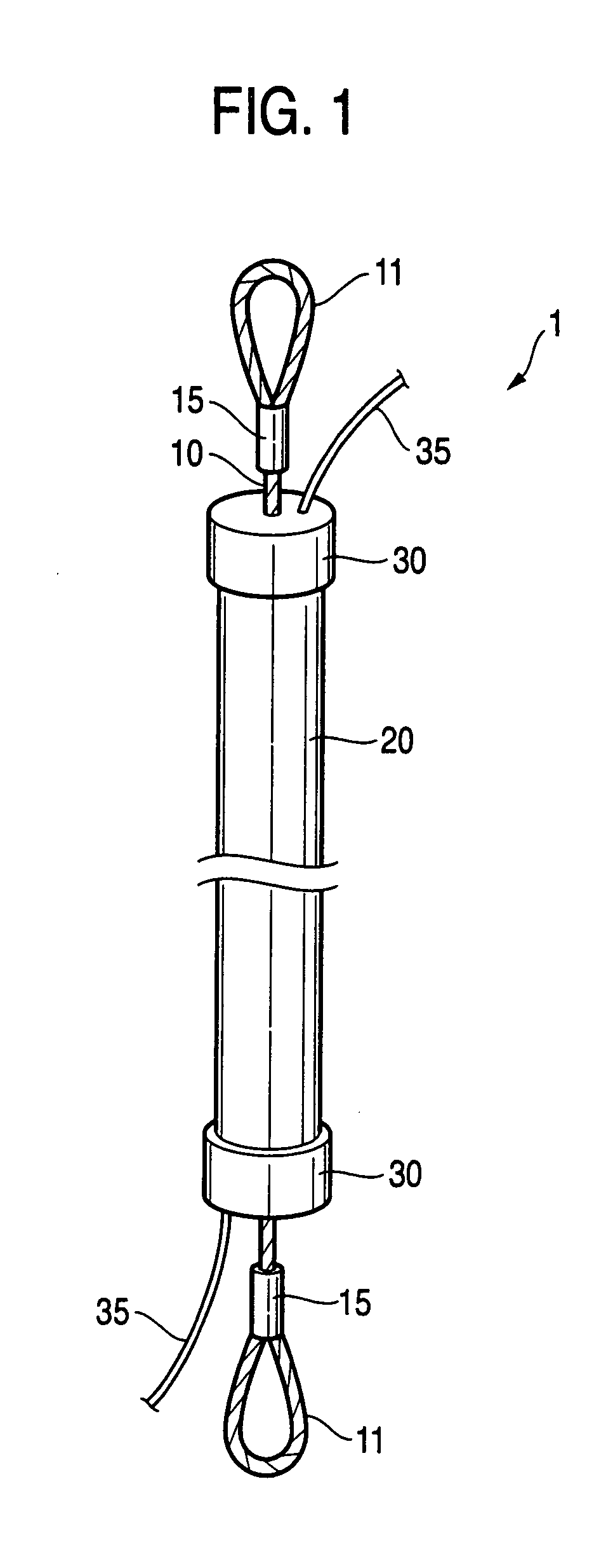
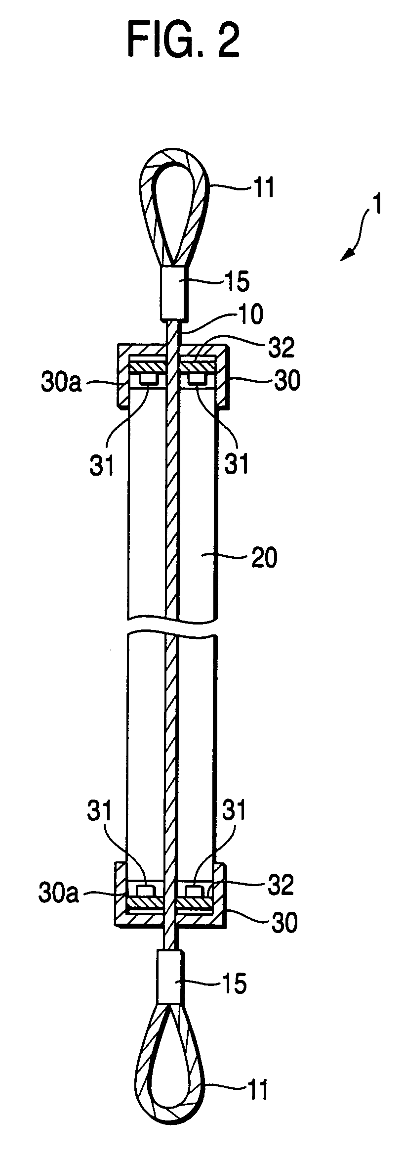
[0094]FIG. 1 is a perspective view of a linear luminous body 1 according to an embodiment of the invention. FIG. 2 is a longitudinal sectional view showing the internal structure of the linear luminous body 1. For example, the linear luminous body 1 is used as a partition.
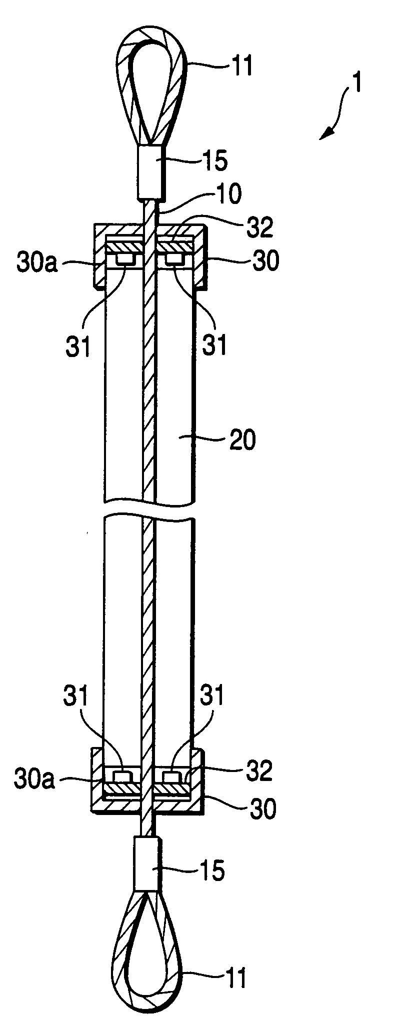
[0095]Roughly, the linear luminous body 1 includes a wire rope 10, a light guide 20, and light source units 30. The wire rope 10 is braided from a plurality of wires made of stainless steel The wire rope 10 has a diameter of about 2 mm and a total length of about 2 m. Hooks 11 are formed at upper and lower ends of the wire rope 10 respectively so that the hooks 11 are used for installation of the linear luminous body 1.
[0096]The wire rope 10 except its upper and lower end portions is covered with the light guide 20 so that the wire rope 10 passes through the center of the light guide 20. The light guide 20 is a columnar member made of a silicone resin containing silica as a light-diffusing agent. The light source u...
embodiment 2
[0100]Another embodiment of the invention will be described below with reference to FIG. 4. FIG. 4 is a sectional view of a linear luminous body 2 according to this embodiment. Incidentally, parts the same as those in the previous embodiment are denoted by the same reference numerals as those in the previous embodiment and the description of the parts will be omitted.
[0101]In the linear luminous body 2, a light-reflective layer (light-reflecting film) 16 is formed on a surface of the wire rope 10. The light-reflecting film 16 is formed to have an early uniform thickness on the whole. Accordingly, the surface shape of the light-reflecting film 16 reflects the surface shape of the wire rope 10. On the other hand, a light guide 25 is a columnar member made of a silicone resin. Incidentally, the light guide 25 does not particularly contain any light-diffusing agent as an additive.
[0102]The linear luminous body 2 is produced as follows. First, a wire rope 10 of stainless steel is produce...
embodiment 3
[0104]Next, a luminous structure of the invention as Embodiment 3 will be described below with reference to FIG. 5A through 9C.
[0105]FIG. 5A is a perspective view of a basic structure of a linear luminous structure 101 according to an embodiment of the invention FIG. 5B is a view showing an example of the linear luminous structure 101 having light guides combined on a plane so as shaped like a cross in the square, forming a Chinese character. FIG. 6 is a longitudinal sectional view showing the internal structure of the linear luminous structure 101. For example, the linear luminous structure 101 is used as a character advertisement.
[0106]Roughly, the linear luminous structure 101 includes connectors 110 served as light source accommodating portion, light source units 120, and light guides 130. The connectors 110 can be shaped variously according to the combination of line segments. That is, the connectors 110 having various shapes such as a straight line shape, an L shape, a T shape...
PUM
 Abstract
Description
Claims
Application Information
 - R&D
- Intellectual Property
- Life Sciences
- Materials
- Tech Scout
- Unparalleled Data Quality
- Higher Quality Content
- 60% Fewer Hallucinations
Browse by: Latest US Patents, China's latest patents, Technical Efficacy Thesaurus, Application Domain, Technology Topic, Popular Technical Reports.
© 2025 PatSnap. All rights reserved.Legal|Privacy policy|Modern Slavery Act Transparency Statement|Sitemap|About US| Contact US: help@patsnap.com


