Compact reactor

a reactor and compact technology, applied in the field of chemical engineering, can solve the problems of crude tracking of the maximum reaction rate curve, relatively high creation bed volume, and high cost of catalysts

Inactive Publication Date: 2006-04-04
MEGGIT (UK) LTD
View PDF27 Cites 41 Cited by
  • Summary
  • Abstract
  • Description
  • Claims
  • Application Information

AI Technical Summary

Benefits of technology

[0024]The reactor may be one in which a particulate material is to be confined within the reaction zone, e.g. catalyst, and at least one wall boun

Problems solved by technology

Ammonia synthesis typically takes place at high pressures, greater than 100 bar and therefore creating bed volume is relatively expensive.
Furthermore, the catalyst itself is costly.
In prior art converters though, only a very crude tracking of the maximum reaction rate curve is achievable in the reactor, due to the

Method used


Image

  • Compact reactor
  • Compact reactor
  • Compact reactor

Examples


Embodiment Construction

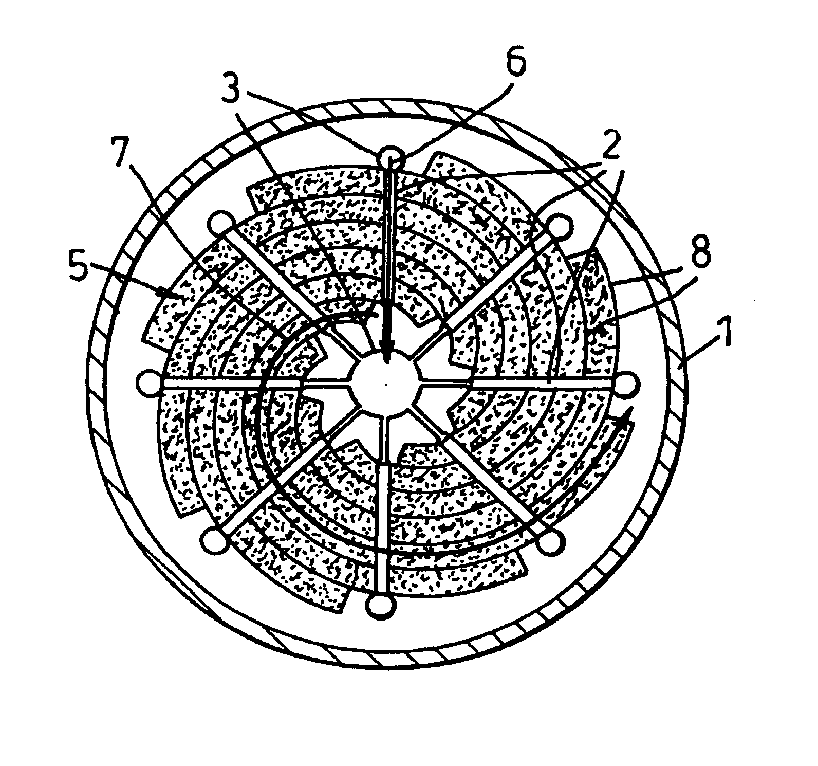
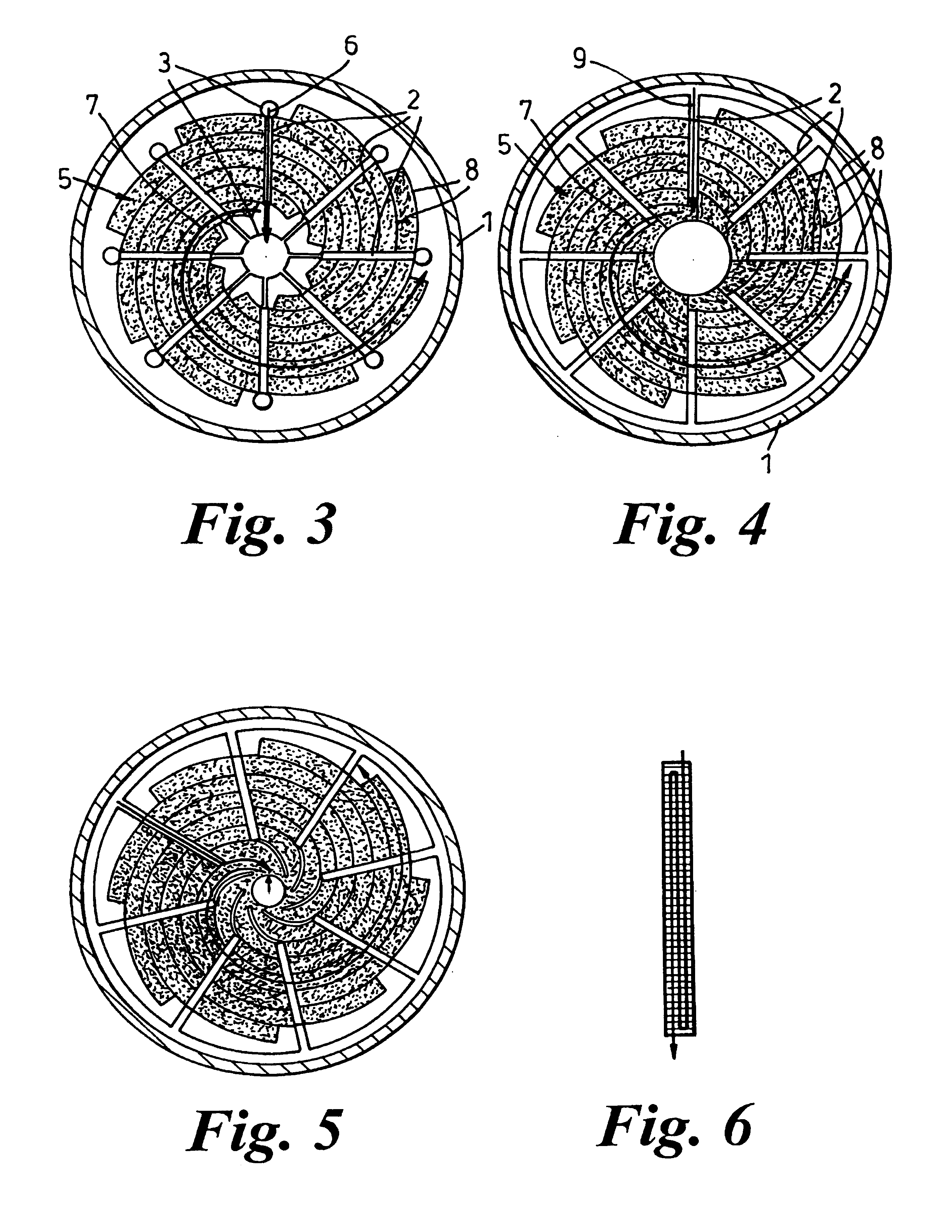
[0047]The general principle of the spiral / radial flow reactor is illustrated in FIG. 3. This shows a containment shell 1 wherein eight PCHE cores 2 are configured in a radial pattern, evenly spaced around the central axis of the containment shell 1. At each end of each PCHE core 2 is a cooling medium manifold 3. The manifold 3 at the central axis of the containment shell 1 is universal to all the PCHE cores 2.

[0048]Beds of catalyst 5 are located between the PCHE cores 2, beginning at the inner end of the PCHE cores 2 and are curved such that each subsequent bed 5 is radially further from the longitudinal axis of the containment shell 1 so forming a spiral. A different spiral of catalyst bed 5 begins at the inner end of each of the PCHE cores 2. Catalyst beds forming part of one spiral are separated from those of other spirals by baffles 8. As the beds 5 are arranged in a spiral pattern between the PCHE cores 2, the effective path length through a catalytic bed 5 between heat exchang...


PUM

PropertyMeasurementUnit
Flow rateaaaaaaaaaa

Abstract

A reactor comprises a plurality of reaction zones divided by heat exchanger panels but in fluid communication via the panels, the reaction zones being arranged in a spiral configuration whereby the reaction zones form a flow path for reactants that extends between a central part of the reactor and an outer peripheral part thereof.

Description

CROSS-REFERENCE TO RELATED APPLICATIONS[0001]This application claims priority under 35 U.S.C. §119(e) to U.S. Provisional Patent Application No. 60 / 184,007, entitled Catalytic Bed Reactor, filed Feb. 22, 2000, and under 35 USC §119(a) to G.B. 0001699.8, filed Jan. 25, 2000 and G.B. 0017189.2, filed Jul. 13, 2000, the entirety of each of which is incorporated herein by reference.FIELD OF THE INVENTION[0002]The present invention is applicable in the field of chemical engineering and especially relates to improvements in chemical reactors. In general the invention relates to control of the reactant temperature during an exothermic or endothermic reaction. Particularly the invention provides a printed circuit reactor system (PCR) and process control method which is intended to provide that the reactants are kept as close as practicable to a temperature at which the reaction rate will be optimum for a given product content.BACKGROUND OF THE INVENTION[0003]Control of the temperature of re...

Claims


Application Information

Patent Timeline
IPC IPC(8): F28D7/00B01J8/02B01J8/04C01C1/04
CPCB01J8/0221B01J8/0285B01J8/0292B01J8/0438B01J8/0496C01C1/0417B01J8/0235F28F2260/00B01J2208/0015B01J2208/00212B01J2208/00221B01J2219/00085B01J2219/182F28D9/04F28F3/048Y02P20/52
Inventor JOHNSTON, ANTHONY
Owner MEGGIT (UK) LTD
Why Eureka
Try Eureka