Gain compensation for optocoupler feedback circuit

a gain compensation and feedback technology, applied in the direction of electric variable regulation, instruments, semiconductor lasers, etc., can solve the problems of increasing or decreasing the current transfer ratio of the optocoupler, introducing undesirable variations in performance and capability, and affecting the device li

Active Publication Date: 2006-04-04
TEXAS INSTR INC
View PDF2 Cites 7 Cited by
  • Summary
  • Abstract
  • Description
  • Claims
  • Application Information

AI Technical Summary

Benefits of technology

[0023]In the present invention, the gain setting resistor has an effective value that is raised when the current transfer ratio increases and is decreased as the current transfer ratio decreases. This results in the overall gain of the circuit being held constant and independent of the current transfer gain.
[0024]The present invention accomplishes the advantages set forth above, in the preferred embodiment, by a small number of parts added to the feedback circuit to establish a constant crossover frequency feedback loop.

Problems solved by technology

The CTR range variation introduces undesirable variations in performance and capability of a circuit that must transmit information across the isolation barrier.
However, the current transfer ratio of the optocoupler increases or decreases with changes in temperature, and it also suffers a degradation over the life of the device.
Lower performance from the isolated feedback loop results, along with a degraded performance of the optocoupler.
Instead, a margin for error for these changes is built into the circuit.

Method used


Image

  • Gain compensation for optocoupler feedback circuit
  • Gain compensation for optocoupler feedback circuit
  • Gain compensation for optocoupler feedback circuit

Examples


Embodiment Construction

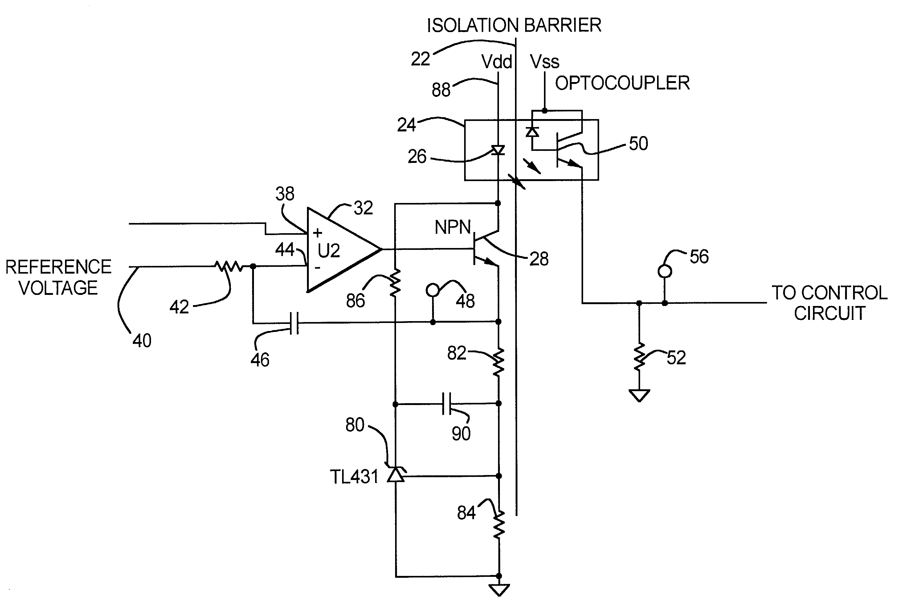
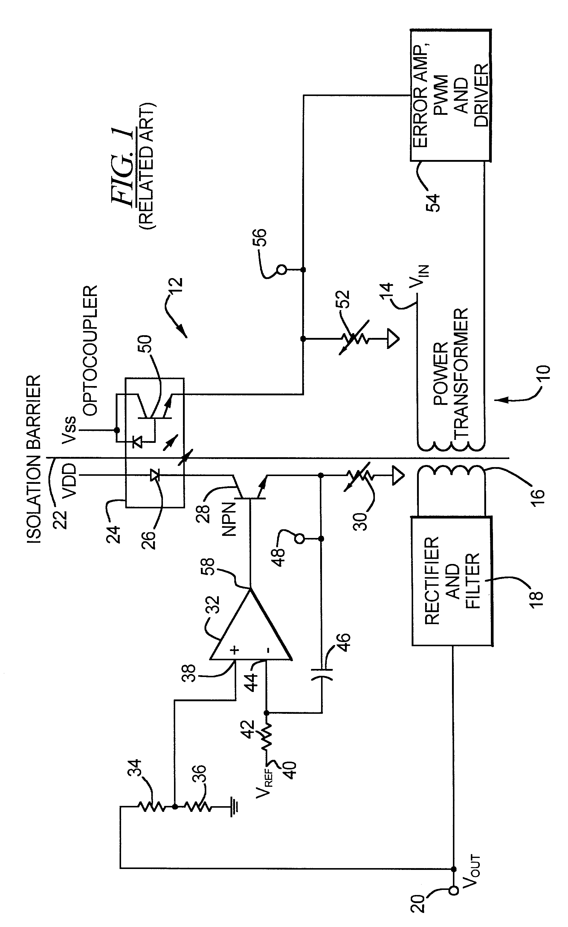
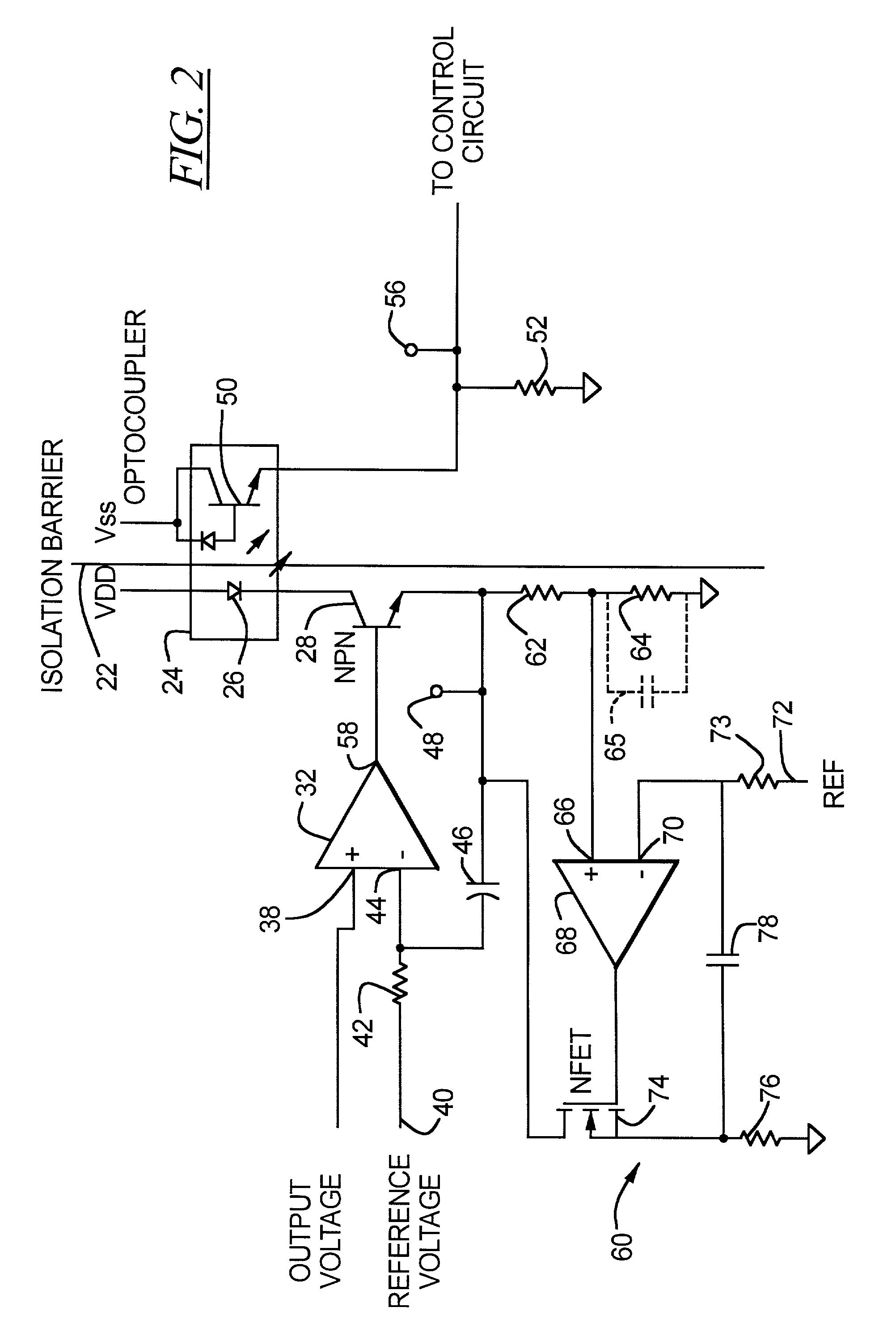
[0030]In FIG. 2, only the feedback circuit is shown. The feedback circuit may be used with a power supply as shown in FIG. 1, or may be used with any other circuit for which a fixed gain feedback would benefit. The elements which are common to FIG. 1 are shown with the same reference characters. The voltage at the test point 56 to the control circuit is recognized as a fairly constant DC value. Using this assumption, a compensation is made for the variations in the current transfer ratio of the optocoupler 24. A circuit 60 is added to replace the trim resistor 30 with a resistor 62 and a resistor 64 to form a voltage divider that senses the current through the light emitting diode 26 of the optocoupler 24. The voltage at the midpoint (the physical midpoint, but not necessarily electrical midpoint) of the voltage divider 62 and 64 is connected to a non-inverting input 66 of a operational amplifier 68, the inverting input 70 of which is connected to a reference voltage 72. A resistor ...


PUM


Abstract

A feedback circuit has an optical coupler with a feedback gain control. The feedback gain control includes an active element connected to vary current flow depending on changes in gain of the optical coupler.

Description

BACKGROUND OF THE INVENTION[0001]1. Field of the Invention[0002]The present invention relates generally to an optical coupler circuit, and, in particular, to a gain compensation circuit for an optical coupler.[0003]2. Description of the Related Art[0004]Optical coupler circuits, also referred to as optically coupled isolator devices or optocouplers, provide isolation between different circuit portions which, for example, operate at vastly different voltages. An optocoupler typically includes a light source, such as an LED, at one side and a light sensor, such as a phototransistor or a photodiode, at the other side. Changing light levels from the LED traverses a gap and are received by the light sensor. The imaginary division between the circuit portions operating at the two different voltages is referred to as an isolation barrier and the optocoupler communicates across this isolation barrier. The current gain of an optical coupler between the input and the output is referred to as ...

Claims


Application Information

Patent Timeline
Patent Type & Authority Patents(United States)
IPC IPC(8): G02B27/00H01S5/042H01S5/0683H03G3/30
CPCH03G3/3084H01S5/042H01S5/0683
Inventor WILLIAMS, DAVID A.AMARO, MICHAEL G.
Owner TEXAS INSTR INC
Why Eureka
Try Eureka