Non-contacting large angle rotary position sensor for rotating shaft

a rotary position sensor and large angle technology, applied in the field of magnetic position sensors, can solve the problems of deteriorating signal integrity, wear and corrosion of prior art potentiometers, etc., and achieve the effect of easy identification of the amount of movemen

Inactive Publication Date: 2006-04-04
CONTINENTAL AUTOMOTIVE SYST INC
View PDF12 Cites 7 Cited by
  • Summary
  • Abstract
  • Description
  • Claims
  • Application Information

AI Technical Summary

Benefits of technology

[0010]In a most preferred embodiment of this invention, the cam follower pivots along the cam with the magnet mounted on the pivoting point. The magnet has a cr...

Problems solved by technology

One challenge with this type system is that the prior art potentiometers are susceptible to we...

Method used


Image

  • Non-contacting large angle rotary position sensor for rotating shaft
  • Non-contacting large angle rotary position sensor for rotating shaft
  • Non-contacting large angle rotary position sensor for rotating shaft

Examples


Embodiment Construction

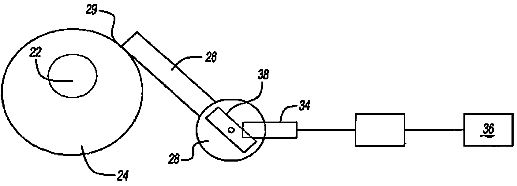
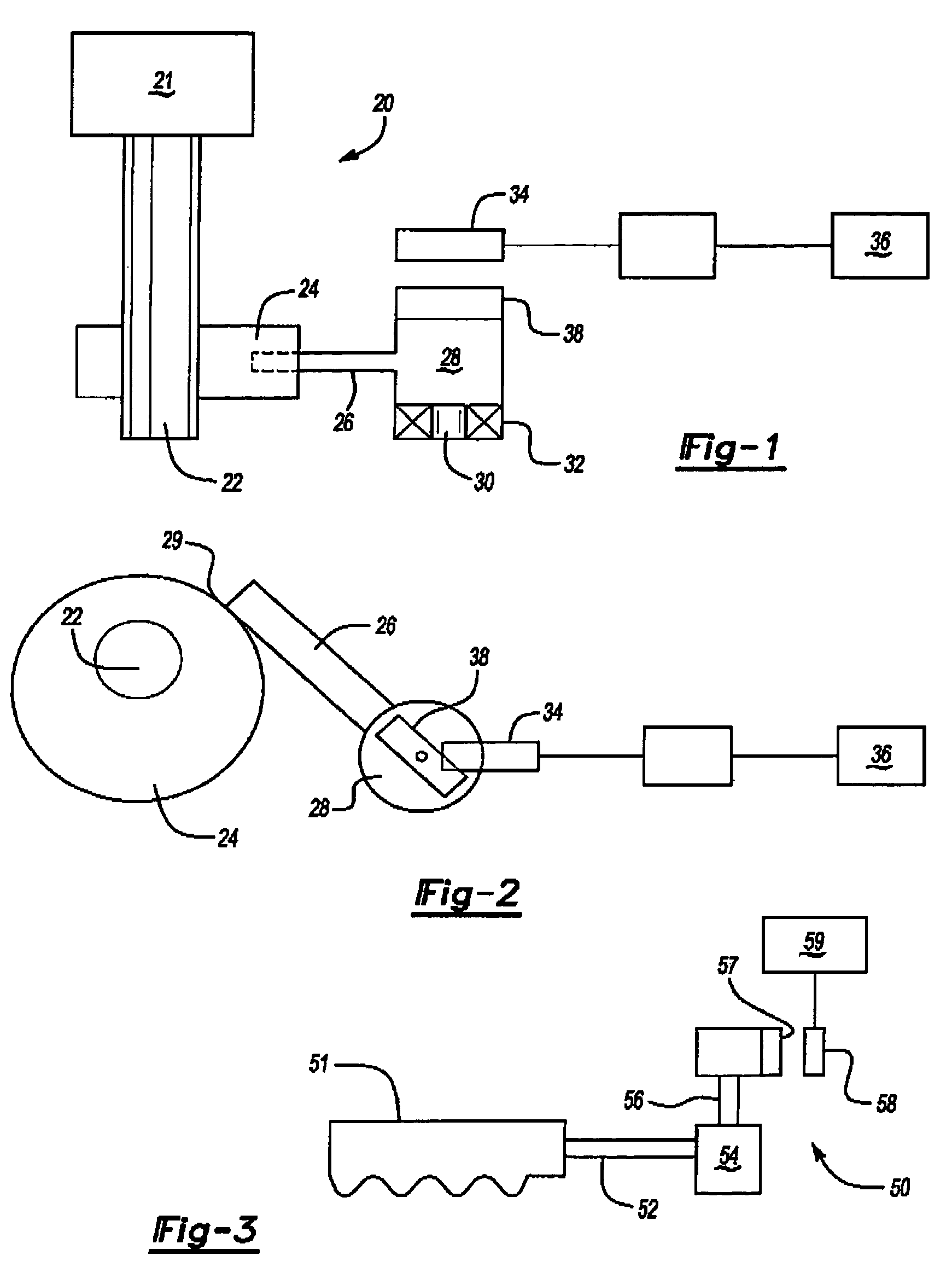
[0022]FIG. 1 shows a control system 20 including a component 21 having a control input which in turn rotates a control shaft 22. A cam 24 turns with shaft 22. As cam 24 turns, it drives a pivoting cam 26. As pivoting cam 26 moves along cam 24, it pivots about a pivot point 28. As is shown, the pivot point 28 includes a pin 30 to cantilever mount the pivot point 28 such as in a bearing 32. A magnet 38 is positioned on the pivot point 28 and the movement of the magnet is sensed by a magnetic transducer 34. The magnetic transducer 34 communicates with a control such as an ECU 36.

[0023]When an operator wishes to apply a control feature to a system such as an engine incorporating the system 20, a control input is placed an the component. The control input results in a particular amount of rotation of the shaft 22, and that shaft rotation is sensed by the magnetic transducer 34.

[0024]As shown in FIG. 2, shaft 22 has its cam 24 driving the pivoting cam 26. A point 29 rides along the cam 24...


PUM


Abstract

A rotation sensor provides a control with an indication of shaft position. The sensor utilizes a magnetic connection between a cam follower and a transducer. The magnetic connection eliminates problems in the prior art such as degradation due to wear and corrosion. In particular, a rotating shaft carries a cam. The cam drives a cam follower. As the cam follower moves, a magnet moves. The transducer can sense movement of this magnet. In preferred embodiments, the cam follower is driven to pivot and the magnet is mounted on the pivot point of the cam follower. The present invention is disclosed for use in motorcycle throttle handles, accelerator pedals, brake pedals, and detecting shaft position for valve timing.

Description

[0001]The present invention claims priority to U.S. Provisional Patent Application Ser. No. 60 / 389,586 filed on Jun. 18, 2002.BACKGROUND OF THE INVENTION[0002]This invention relates to a magnetic position sensor that is particularly useful for a rotating control shaft.[0003]Several systems use a rotating shaft to transmit a control input to a controller. As an example, motorcycle throttle handles, accelerator and brake pedals, etc. In each of these systems, an operator inputs a desired control signal through a rotating shaft.[0004]Other type systems provide control feedback by a rotating shaft position. One example is a system for controlling variable valve timing based upon a rotating shaft position.[0005]While historically many of these control signals have been transmitted through a hard connection such as a cable or wire, more recently these signals have been transmitted electrically. As an example, a variable resistance potentiometer has moving fingers that move along conductiv...

Claims


Application Information

Patent Timeline
IPC IPC(8): G01B7/30G01D5/04G01D5/14G01D5/16
CPCG01D5/145G01D5/04
Inventor SPELLMAN, JR., CHARLES A.
Owner CONTINENTAL AUTOMOTIVE SYST INC
Why Eureka
Try Eureka