Electromagnetic field generation antenna for a transponder

a transponder and electromagnetic field technology, applied in the direction of antennas, burglar alarms by hand-held items removal, antenna supports/mountings, etc., can solve the problems of increasing the necessary system excitation power, insufficient magnetic field to properly remotely supply the transponder, and generally limited range of conventional transponder systems, so as to improve the range and/or the signal level available, optimize the impedance matching, and improve the terminal efficiency

Inactive Publication Date: 2006-04-04
STMICROELECTRONICS SRL
View PDF115 Cites 39 Cited by
  • Summary
  • Abstract
  • Description
  • Claims
  • Application Information

AI Technical Summary

Benefits of technology

[0018]The present invention more specifically aims at improving the terminal efficiency, especially by optimizing the impedance matching of the oscillating circuit.
[0019]The present invention aims, in particular, at improving the range and/

Problems solved by technology

Conventional transponder systems generally have a limited range, that is, at a certain distance (d, FIG. 2) from the terminal, the magnetic field is insufficient to properly remotely supply a transponder.
A first disadvantage of such a solution is that it increases the necessary system excitation power.
A second disadvantage of such a solution is that such a current increase remains limited by the generator structure and requires components having significant size (in particular, a large cross-section of the conductor forming antenna L1).
However, this solution still ca

Method used


Image

  • Electromagnetic field generation antenna for a transponder
  • Electromagnetic field generation antenna for a transponder
  • Electromagnetic field generation antenna for a transponder

Examples


first embodiment

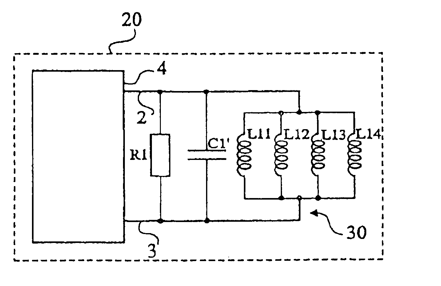
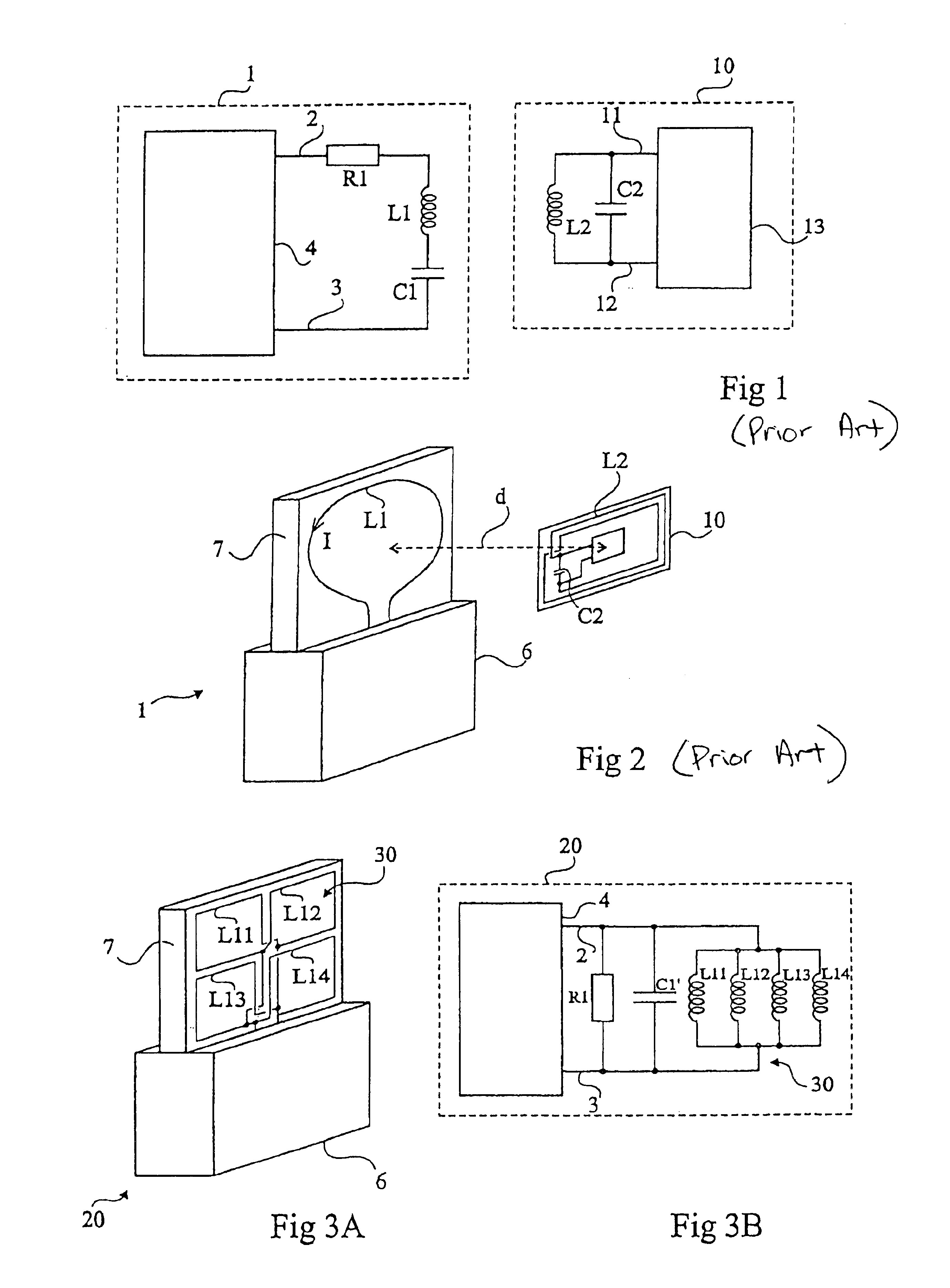
[0039]FIGS. 3A and 3B very schematically show a terminal for generating an electromagnetic field according to the present invention. FIG. 3A illustrates an example of a structural implementation to be compared with the representation of FIG. 2. FIG. 3B shows the equivalent electric diagram to be compared with the representation of FIG. 1.

[0040]A terminal 20 according to the present invention differs from a conventional terminal by its oscillating circuit. For the rest, it includes circuits 4 for controlling, exploiting, and processing data, a base 6, and a support 7 for the antenna, for example, a printed circuit wafer on which are made the conductive tracks forming the antenna.

[0041]According to the present invention, antenna 30 of the oscillating circuit is formed of several coplanar and non-concentric cells or loops, which are placed or formed side by side on support 7, each cell being formed of one or several coplanar concentric turns. Electrically, this amounts to providing sev...

second embodiment

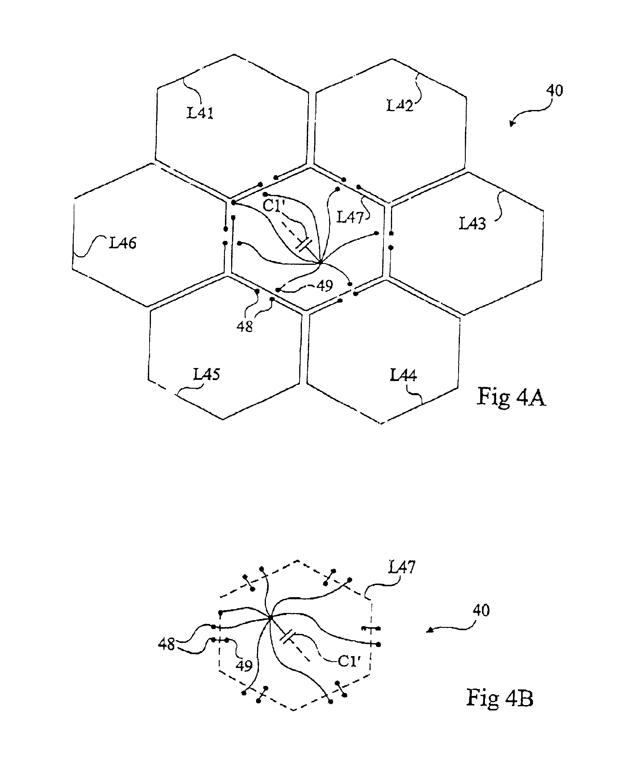
[0051]FIGS. 4A and 4B schematically show, respectively by a view from a first surface and from a second opposite surface, an antenna 40 according to the present invention. The cells are placed in a “honeycomb”. For example, six cells L41, L42, L43, L44, L45, and L46 having the shape of a hexagonal spiral are arranged around a seventh cell L47 also in the form of a hexagonal spiral. Such a structure optimizes the homogeneity of the field lines. FIG. 4A shows, for example, the first surface of a printed circuit on which are formed the different cells of antenna 40 and FIG. 4B shows, for example, the second surface of this circuit enabling obtaining the interconnections. A capacitor C1 is either external or formed in the printed circuit (for example, across its thickness). The two ends of each spiral L41, L42, L43, L44, L45, and L46 and one end of central spiral L47 are connected to vias 48 enabling crossing of the printed circuit. The first ends are connected to a first electrode of c...


PUM


Abstract

An antenna for generating an electromagnetic field including several planar inductive cells parallel connected in an array and forming, in association with at least one capacitor, an oscillating circuit adapted to being excited by a high-frequency signal.

Description

BACKGROUND OF THE INVENTION[0001]1. Field of the Invention[0002]The present invention relates to systems using electromagnetic transponders, that is, transmitters and / or receivers (generally mobile) capable of being interrogated in a contactless and wireless manner by a unit (generally fixed), called a read and / or write terminal. Generally, transponders extract the power supply required by the electronic circuits included therein from the high-frequency field radiated by an antenna of the read and write terminal. The present invention applies to such systems, be they read-only systems, that is, including a terminal only reading the data from one or several transponders, or read / write systems, in which the transponders contain data that can be modified by the terminal.[0003]2. Discussion of the Related Art[0004]Systems using electromagnetic transponders are based on the use of oscillating circuits including a winding forming an antenna, on the transponder side and on the read / write t...

Claims


Application Information

Patent Timeline
IPC IPC(8): H01Q9/00H01Q1/22H01Q7/00
CPCH01Q1/22H01Q7/005H01Q1/2216
Inventor WUIDART, LUCBARDOUILLET, MICHEL
Owner STMICROELECTRONICS SRL
Why Eureka
Try Eureka