Laser distance measuring device with phase delay measurement

Inactive Publication Date: 2006-04-04
HILTI AG +1
View PDF14 Cites 65 Cited by
  • Summary
  • Abstract
  • Description
  • Claims
  • Application Information

AI Technical Summary

Benefits of technology

[0017]Advantageously, the third step influences the first step due to a feedback regulated by the microcontroller, whereby the low frequency signal can be modif

Problems solved by technology

In addition, the interference modulation components are dependent on and aging, so that an initial calibration and the use of correction tables for troubleshootin

Method used


Image

  • Laser distance measuring device with phase delay measurement
  • Laser distance measuring device with phase delay measurement
  • Laser distance measuring device with phase delay measurement

Examples


Embodiment Construction

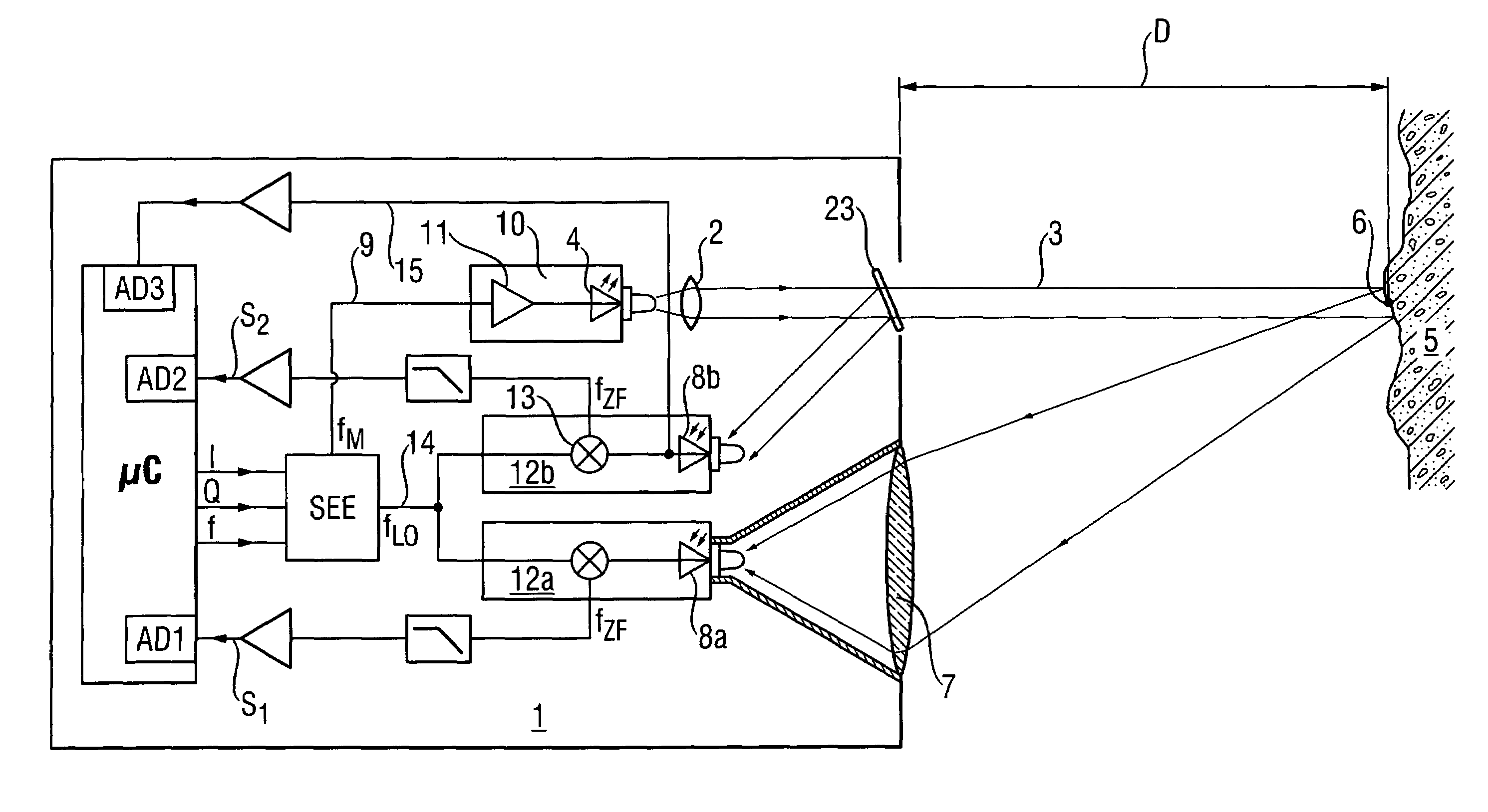
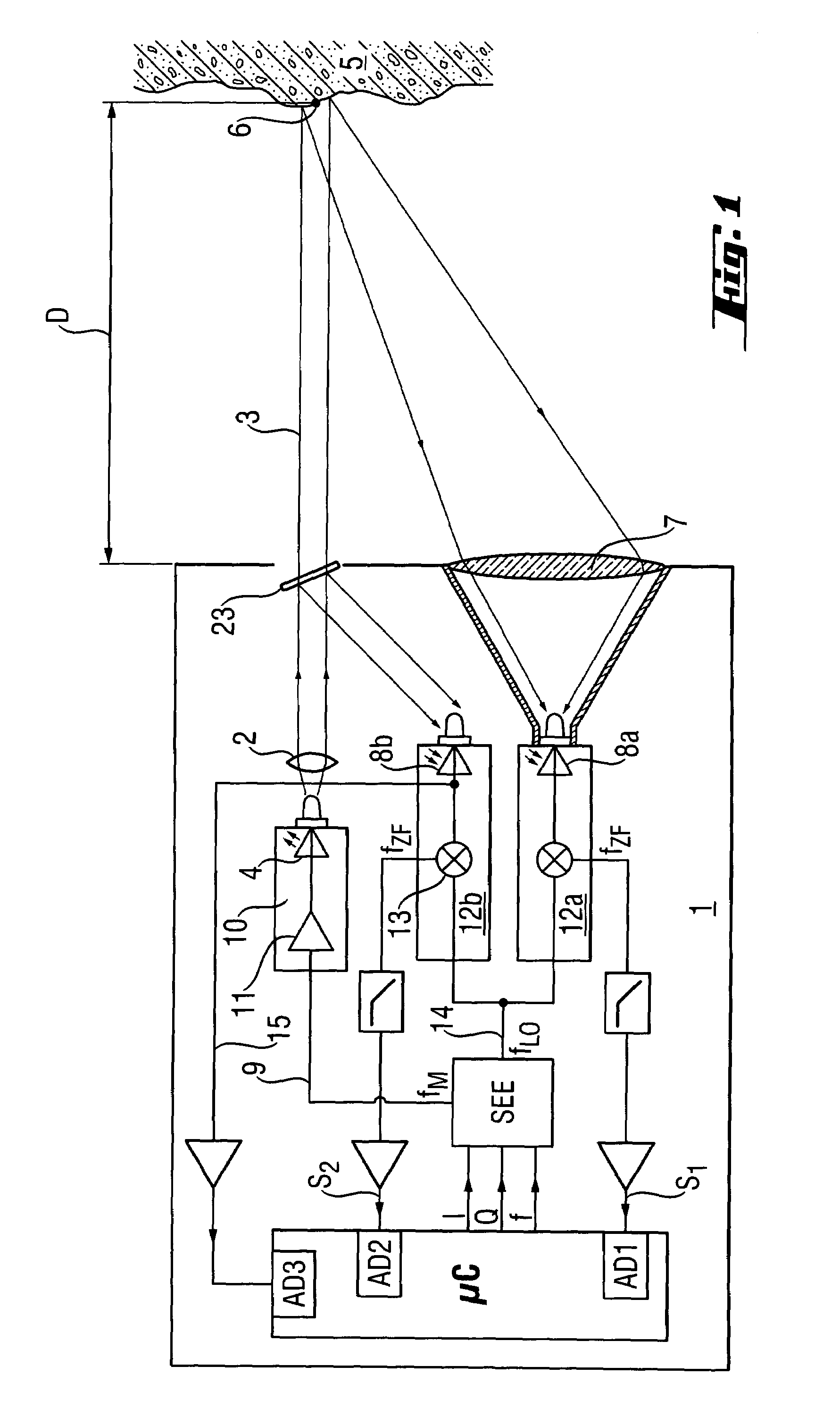
[0029]According to FIG. 1, in an opto-electronic distance measuring device 1, a measurement light beam 3 emitted by a laser diode 4 and bundled by a collimation optic 2 is directed at a measurement object 5. The measurement light beam 3 generates a light point 6 on the surface of the measurement object 5 . The scattered light from this light point 6 is focussed using a receiver optics 7 onto a photosensitive surface of a first receiving photodetector 8a configured as a photodiode. For determining the distance D from the distance measuring device 1 to the measurement object 5, a high frequency measurement signal 9 is superimposed on the measurement light beam 3 of the laser diode 4. As a measurement method, a phase delay process is used which is based on a periodic, intensity-modulated emitted laser radiation. Herein, the emitter 10 is impinged upon with the measurement signal 9 of a signal generation unit SEE having the measurement frequency fM, wherein the emitted light output is m...


PUM


Abstract

A laser distance measuring device (1) includes a laser diode (4) for emitting a high frequency intensity modulated measurement light beam (3) and connected with a signal generating unit (SGU) that generates a high frequency measurement signal (9) for high frequency signal transfer, at least one receiver photodetector (8a) for receiving a measurement light beam (3) reflected from a measurement object (5) and connected to a high frequency demodulator (13) for generating a low frequency phase delay signal (S1) containing phase information of the reflected intensity modulated measurement light beam (3), and a microcontroller (μC) for calculating a distance (D) from the phase delay signal (S1) and connected to the high frequency demodulator (13), with the microcontroller (μC) being connected to a control photodetector (8c) arranged in the measurement light beam (3) for low frequency transfer for determining an interference modulation component.

Description

BACKGROUND OF THE INVENTION[0001]1. Field of the Invention[0002]The invention relates to an opto-electronic distance measuring device with an intensity modulated measurement light beam based on the principle of phase delay measurement[0003]2. Description of the Prior Art[0004]Such opto-electronic distance measuring devices are suitable for measurement on technical surfaces, that is, they can be used without the use of defined targets. For determining the distance from a laser diode to an object being measured and from the object to the photodiode, an intensity of a measurement light beam of the laser diode is, as a rule, modulated, i.e., a measurement signal with a high measurement frequency heterodynes the measurement light beam. A phase delay process, in which a periodic, intensity-modulated emitted laser radiation is used, is now used in the majority of the current precise opto-electronic distance measuring devices. The distance is obtained from the measurement of the phase diffe...

Claims


Application Information

Patent Timeline
IPC IPC(8): G01C3/08G01S7/4911G01S7/4915G01S7/497G01S17/36
CPCG01S7/497G01S7/4911G01S7/4915G01S17/36
Inventor GOGOLLA, TORSTENWINTER, ANDREASSEIFERT, HELMUT
Owner HILTI AG
Why Eureka
Try Eureka