
Eureka
For R&D, Eureka makes reading and utilizing patents & technical documents easy.
Eureka AIR
Designed for self-driven R&D workflows. Generate viable solutions, solve complex R&D challenges, empower your innovation with AI.

Eureka Materials
Designed for material experts only. Revolutionize your material R&D, from search, analyze, to developing new materials.

TechResearch
Generate reliable direction feasibility study reports for your R&D in just a few steps.

TechSeek
Discover and master advanced knowledge NOW. Basics, ideas, possibilities, all at once.

TechMind
As an expert in R&D Theories, TechMind can generates customized viable solutions instantly.

TechRisk
Analyze your overall solution with one click, know your potential R&D risks in advance.

TechMonitor
Get weekly tech updates, stay abreast of the latest tech innovations and key insights.
Three dimensional optical switches and beam steering modules
- Summary
- Abstract
- Description
- Claims
- Application Information
AI Technical Summary
Benefits of technology
Problems solved by technology
Method used
Image


Examples
first embodiment
[0044]Steering modules can switch a plurality of paths independent of the current configuration of the switch. FIG. 3 depicts a steering module 10 according to the present invention. Module 10 may generally comprise beam steering element 12 configured with at least one pair of deflective elements 14. Photons may enter the module through a collimator 16 and coupled through a first deflective element 18 which may steer the photons along an axis to a second deflective element 20 which may also steer the photons along a second axis. FIG. 4 shows an alternate configuration having one fixed deflective element 22 coupled to a double-gimbaled deflector 24. Both module configurations are capable of steering photons along two axis in a manner substantially parallel to the orientation of the input collimator.
[0045]Generally, the deflective elements are individually addressable, created using MEMs fabrication methods and actuated using a variety of known actuation methods, including but not lim...
third embodiment
[0049]Although, FIG. 5 depicts a switch having horizontally opposed modules, the invention is in no way limited to this configuration. By way of example, FIG. 6A depicts an optical switch 600 according to a second alternative version of the The optical switch 600 may generally include a first beam steering module 602 optically coupled to a second beam steering module 604 via a fold deflector 610. First and second sets of optical fibers 601, 605 may be respectively coupled to the first and second modules 602, 604 e.g., via one or more I / O ports. The beam steering modules 602, 604 may respectively include one or more beam steering elements 606, 608 optically coupled to each other via the fold deflector 610. The beam steering elements 606, 608 may deflect one or more optical signals 603 in two dimensions such that an optical signal may be selectively routed between any of the first fibers 601 to any of the second fibers 605 via the fold deflector 610.
[0050]The fold deflector 610 may b...
fourth embodiment
[0063]Many different architectures are possible for the beam steering modules depicted in FIGS. 5-7H. According to the invention a beam steering module may include one or more beam steering elements that deflect optical signals in two dimensions. Such modules can co-operate interchangeably with one or more optical components in an optical beam steering device such as an optical switch, adaptive optics, steered beam optical display, or disk drive. The beam steering elements may include a first deflector array optically coupled to a second deflector array, wherein the first and second deflector arrays co-operate to steer an optical signal in two dimensions.
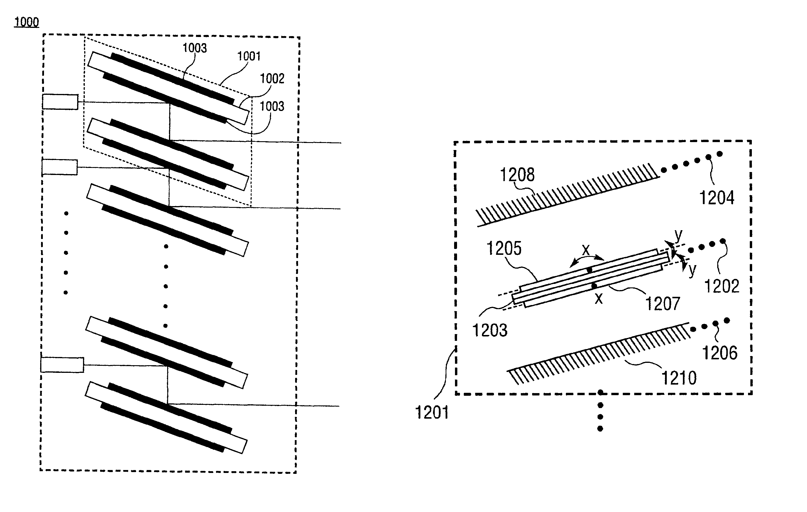
[0064]FIG. 8 depicts a schematic diagram of a first alternative version of an optical module 800 according to a first version of the fourth embodiment of the invention. By way of example, the module 800 may generally include one or more beam steering elements, e.g., a stack of N beam steering elements 8011 . . . 801N. Each beam stee...
PUM
 Abstract
Description
Claims
Application Information
 - R&D Engineer
- R&D Manager
- IP Professional
- Industry Leading Data Capabilities
- Powerful AI technology
- Patent DNA Extraction
Browse by: Latest US Patents, China's latest patents, Technical Efficacy Thesaurus, Application Domain, Technology Topic, Popular Technical Reports.
© 2024 PatSnap. All rights reserved.Legal|Privacy policy|Modern Slavery Act Transparency Statement|Sitemap|About US| Contact US: help@patsnap.com