Reflective variable light attenuator

a variable-type, optical attenuator technology, applied in the direction of optics, polarising elements, instruments, etc., can solve the problems of large number of components, design limitations to the distance between the end of the ferrule and the reflecting mirror, and increase in size, so as to reduce the loss of wavelength-dependent and/or temperature-dependent losses of the main attenuator uni

Inactive Publication Date: 2006-04-04
FDK CORP
View PDF7 Cites 5 Cited by
  • Summary
  • Abstract
  • Description
  • Claims
  • Application Information

AI Technical Summary

Benefits of technology

[0014]In an example of a practical embodiment, the electromagnet is formed of a C-shaped magnetic yoke and a coil wound around the yoke; and the electromagnet is placed in a plane that is parallel to the optical axis such that the C-shaped magnetic yoke surrounds the optical path varying reflector. In this way, it is possible to achieve a variable optical attenuator with a flat structure, and in cooperation with the fact that the attenuator is of the reflection type, the attenuator can...

Problems solved by technology

With such a configuration, however, the number of components becomes large, and a problem involving increase in size arises.
Therefore, there are design limitations to the distance between the end of the ferrule and the reflecting mi...

Method used


Image

  • Reflective variable light attenuator
  • Reflective variable light attenuator
  • Reflective variable light attenuator

Examples


Embodiment Construction

[0022]A preferred embodiment of the present invention is described in detail below with reference to the appended drawings.

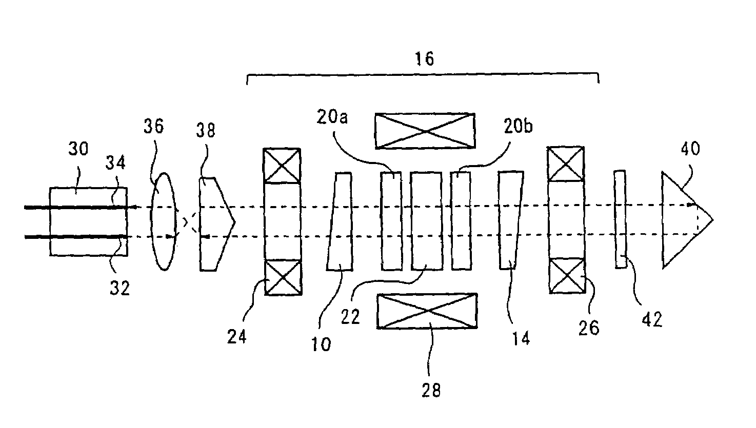
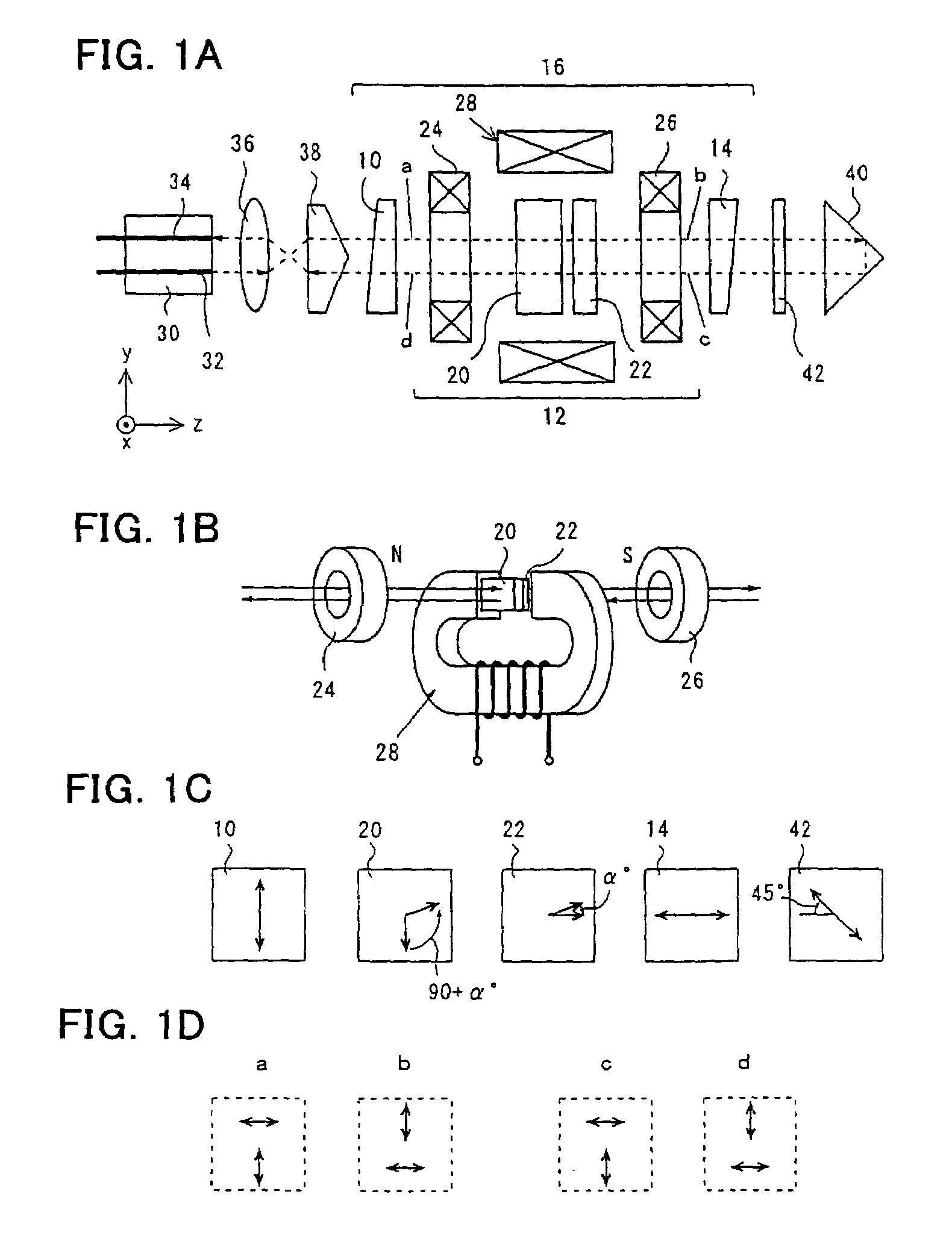
[0023]FIG. 1A to FIG. 1D show an example of a reflection-type variable optical attenuator according to the present invention. FIG. 1A shows a state in which the parts are arranged and an optical path, FIG. 1B shows an example of a specific construction of a Faraday rotational angle varying unit, FIG. 1C shows the directions of the optic axis or the directions of Faraday rotation of each of the optical parts, and FIG. 1D shows the polarization separation state of the forward-path light and the return-path light at positions a, b, c, and d at the front and the rear of the Faraday rotational angle varying unit. It should be noted that an actual optical path is not in a straight line because it is slightly refracted and varied due to, for example, the inclination of the input and output surfaces of the optical parts, the direction of the light beam, and the relation...


PUM


Abstract

A reflection-type variable optical attenuator comprises: a main attenuator unit including a first birefringent crystal plate, a Faraday rotational angle varying unit, and a second birefringent crystal plate arranged in this order; an input port and an output port that are arranged on a side of one end of the main attenuator unit; and a two-point reflection-type optical path varying reflector that is arranged on a side of the other end of the main attenuator unit. Light that comes in from the input port makes a round trip in the main attenuator unit and goes out through the output port.

Description

TECHNICAL FIELD[0001]The present invention relates to a reflection-type variable optical attenuator that is configured by combining a main attenuator unit and an optical path varying reflector such that the light makes a round trip through the main attenuator unit. The optical attenuator is particularly useful when a shutter function to attenuate incoming light at a high rate is required.BACKGROUND ART[0002]Dense wavelength division multiplexing systems (DWDM), for example, used in the optical communication field require optical attenuation and an optical shutter function for the adjustment of the level of signal light amplified by erbium-doped fiber amplifiers (EDFA). A variable optical attenuator is used for such purposes.[0003]Various types of variable optical attenuators have been developed. An opposed-type attenuator is one typical example, and this includes a polarizer and an analyzer, which are wedge-shaped birefringent plates, arranged at both sides (the input side and the o...

Claims


Application Information

Patent Timeline
IPC IPC(8): G02B6/26G02B6/32G02B6/42G02F1/00G02F1/09
CPCG02F1/09G02F2203/48G02F2203/02
Inventor SAHASHI, TERUHISANAKADA, HIDENORIABE, SHOHEIKOJIMA, ISAOIKEDA, KEISUKE
Owner FDK CORP
Why Eureka
Try Eureka