Communication system

a communication system and communication technology, applied in the field of communication systems, can solve the problems of increasing the cost of mobile stations, increasing the power consumption of mobiles, and difficult deployment of base stations

Inactive Publication Date: 2006-04-04
QUALCOMM INC
View PDF11 Cites 35 Cited by
  • Summary
  • Abstract
  • Description
  • Claims
  • Application Information

AI Technical Summary

Benefits of technology

[0014]On receiving an indication of a difference in timing (e.g. from the second mobile station) the network preferably stores that indication for transmission to the first mobile station and / or performs processing on the indication. This may be done, for example, at the first base station, at a dedicated unit or at a base station controller / radio network controller. The processing may be to refine the stored indication of timing difference, for example by processing the received indication together with a previously stored indication to generate a corrected indication that can then be stored for subsequent transmission to the first mobile station. This may allow the accuracy of the stored indication to be maintained even as base station timing drifts.

Problems solved by technology

The requirement for synchronisation in this way makes base stations more difficult to deploy and more expensive to manufacture.
Although this loosely synchronised approach makes it easy to deploy the base stations and reduces their cost it places high demands on the mobile stations.
The need for such powerful search engines will increase the cost of the mobile stations, which is a crucial factor in consumer-oriented mobile telephones, and increase the mobile's power consumption, reducing the standby / talk time of the mobile stations which is also a crucial issue to consumers.
In addition, the synchronisation engines will take a substantial time to measure and process synchronisation information, for example for handover purposes, which may impair the operation of the mobile stations and the network—for example by delaying handovers.

Method used


Image

  • Communication system
  • Communication system
  • Communication system

Examples


Embodiment Construction

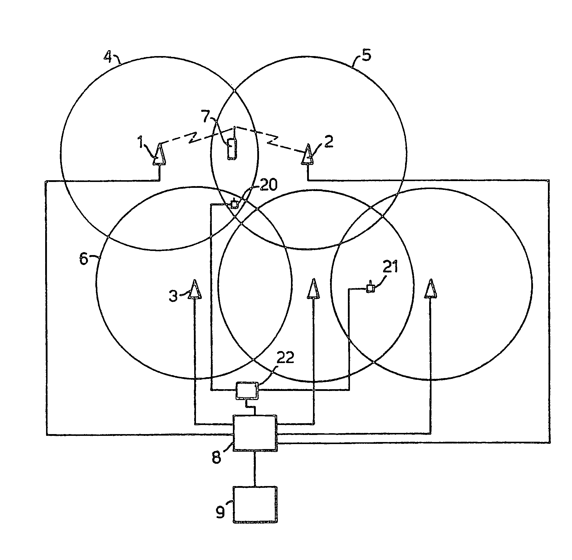
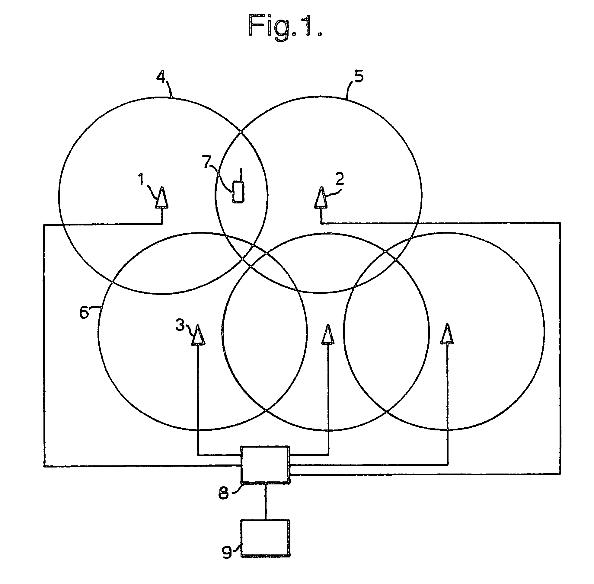
[0030]As explained above, it is proposed that in the W-CDMA system base stations will only be synchronised to the superframe level (720 ms). The present example aims to improve on prior systems by collecting information on the timing differences between neighbouring base stations. This information is then transmitted to the mobile stations. With this information the mobile stations can quickly synchronise with and establish communication with a new base station without the need for a powerful synchronisation engine, or (since less searching of code-time space may be needed) faster (i.e. with reduced search time) and without the need to decode the BCCH of the new base station. Also, this performance improvement can be made without any need to tighten the synchronisation between base stations. Furthermore, as will be described below, the need for TX off slots in inter-frequency and inter-system measurements can be greatly reduced. These factors can potentially reduce the risk of bad q...


PUM


Abstract

A method for distributing timing information in a radio communication system comprising: a network including a plurality of base stations, each capable of transmitting and receiving radio communication signals to and from a respective coverage area, and including a first base station and one or more neighboring base stations whose coverage areas neighbor the coverage area of the first base station; and a first mobile station capable of receiving signals from the first base station; the method comprising: estimating the differences in timing between those base stations; and transmitting indications of those differences in timing to the first mobile station.

Description

[0001]This application claims the benefit of the earlier filed International Application No. PCT / IB99 / 01546, International Filing Date, 7 Sep. 1999, which designated the United States of America, and which international application was published under PCT Article 21(2) in English as WO Publication No. WO 00 / 14907.BACKGROUND OF THE INVENTION[0002]This invention relates to a communication system in which provision is made for the measurement of timing differences between base stations. The present invention is of particular advantage in an asynchronous CDMA (code division multiple access) telephone system.[0003]FIG. 1 shows schematically the configuration of a typical cellular radio telecommunications system. The system comprises a number of base-stations (BSs) 1, 2, 3 etc. Each base-station has a radio transceiver capable of transmitting radio signals to and receiving radio signals from the coverage area or cell 4, 5, 6 etc. next to the base-station. By means of these signals the bas...

Claims


Application Information

Patent Timeline
Patent Type & Authority Patents(United States)
IPC IPC(8): H04Q7/20H04B7/26H04W36/08H04W56/00
CPCH04B7/2668H04W56/002H04W36/08
Inventor OKSANEN, LAURI
Owner QUALCOMM INC
Why Eureka
Try Eureka