
Advanced ion beam detector for ion implantation tools

a technology of ion beam and detector, applied in the field of microstructure fabrication, can solve the problems of reduced production yield and tool utilization, extremely time-consuming re-adjustment procedure, and extremely complex tools, and achieve the effect of increasing accuracy

Active Publication Date: 2006-04-11
ADVANCED MICRO DEVICES INC
View PDF7 Cites 13 Cited by
  • Summary
  • Abstract
  • Description
  • Claims
  • Application Information

AI Technical Summary

Benefits of technology

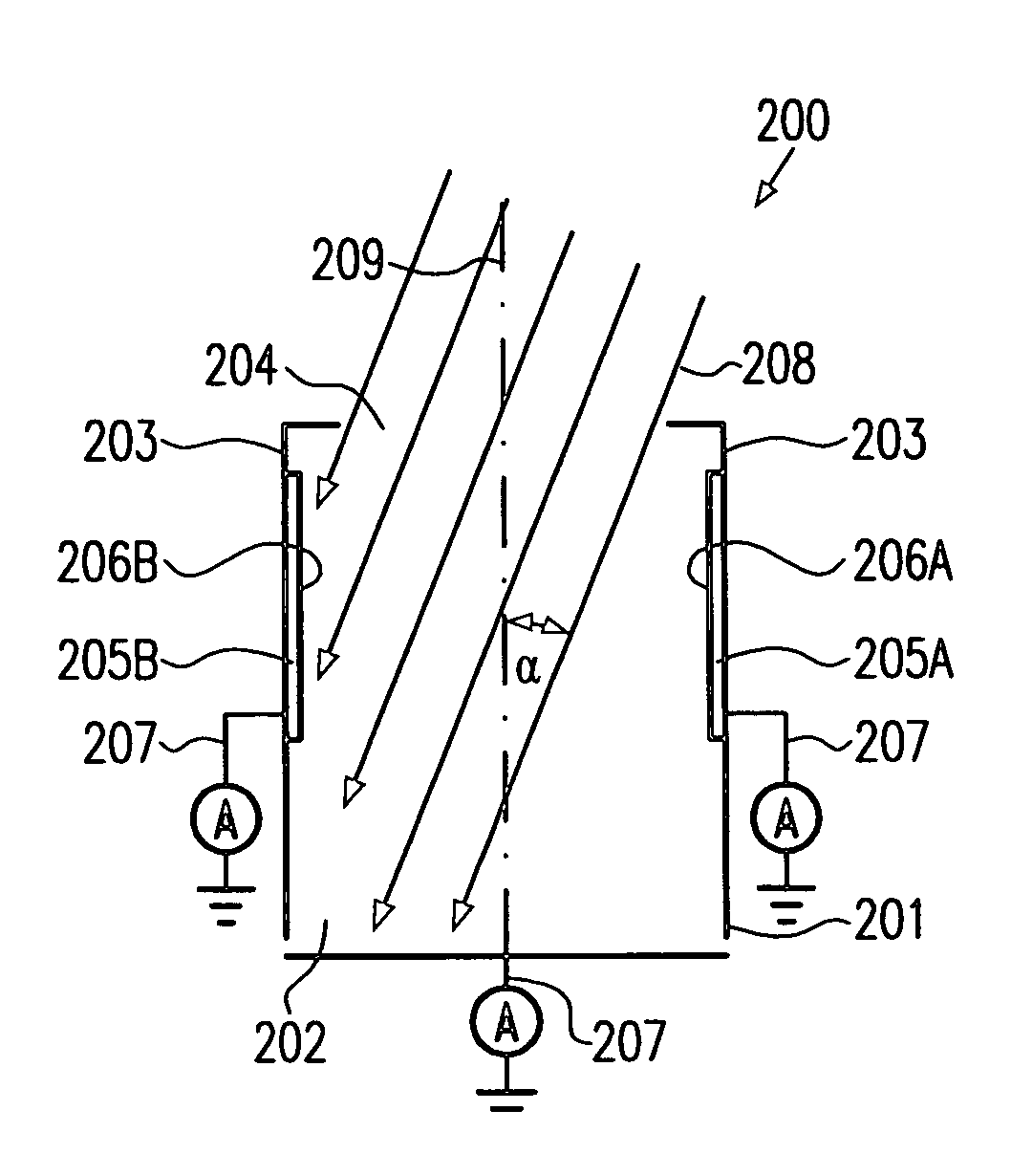
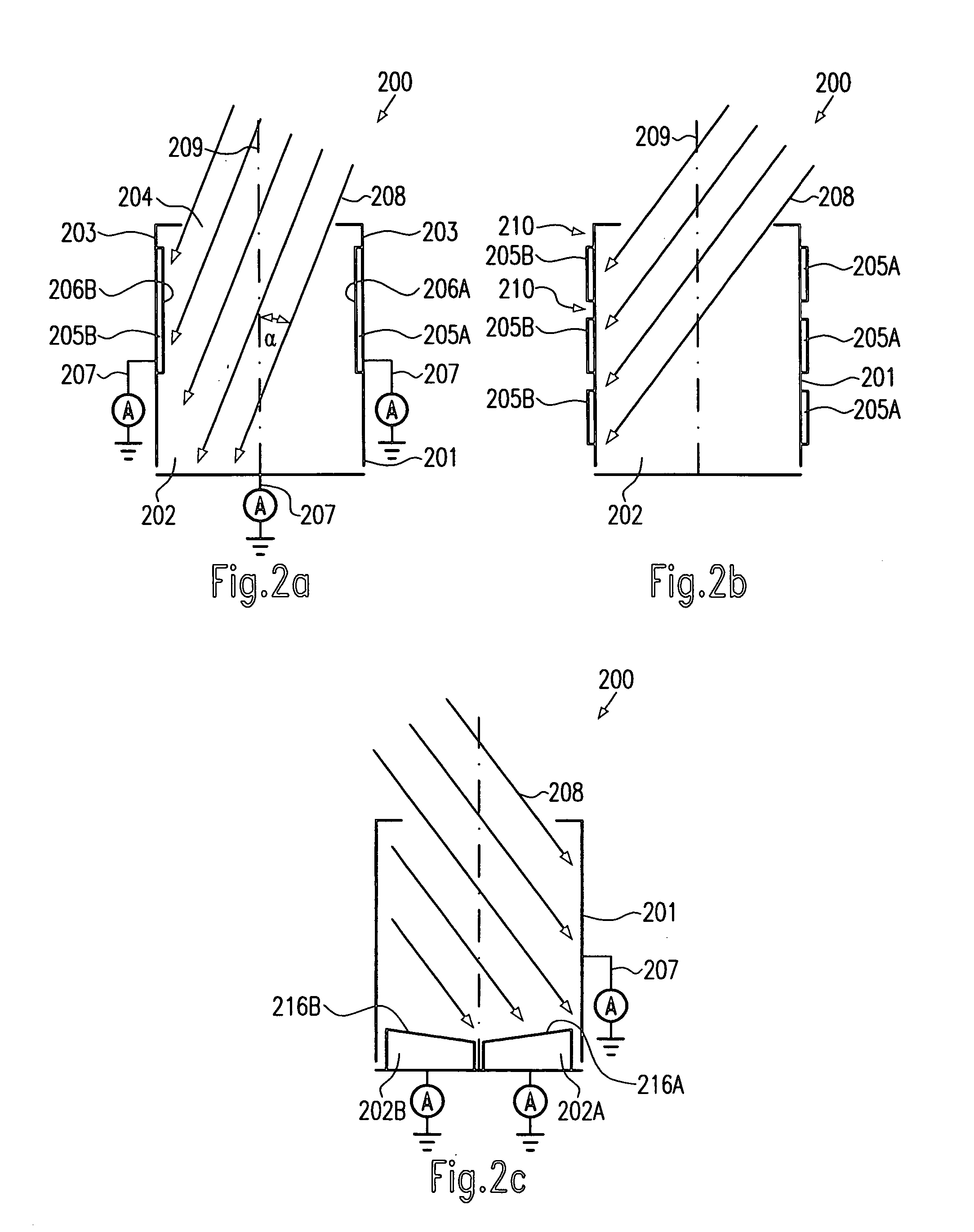
[0013]Generally, the present invention is directed to various systems and methods that allow the observation of a beam shape during the process of adjusting beam parameters. Moreover, an improved Faraday cup design is provided that enables detection of an angle of incidence and / or a beam divergence with increased accuracy, wherein, contrary to a conventional Faraday cup, the inventive Faraday cup is divided into two or more sections that may independently be operated so as to detect portions of an ion beam impinging on the two or more separate portions.

Problems solved by technology

Such tools are extremely complex machines that require continuous monitoring of the machine characteristics so as to achieve high efficiency and machine utilization.
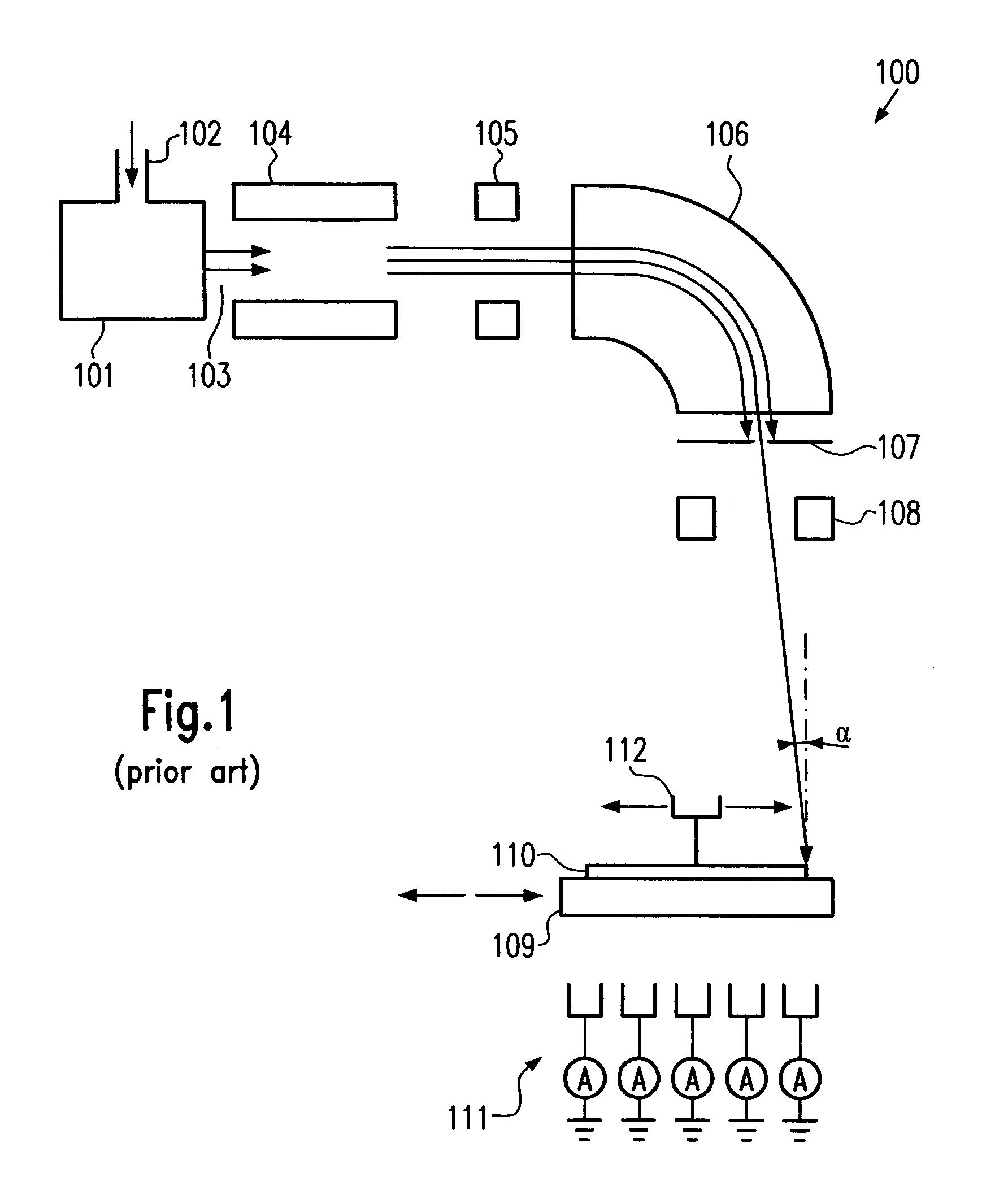
It turns out, however, that any change of an implantation parameter, for example the change of any bias voltages of apertures, minor changes of the settings of the beam shaping elements 105 and 108, and the like, require a thorough check of the beam profile and / or of the parallelism and tilt angle, which may necessitate a scan with the travelling Faraday cup, rendering the re-adjustment procedure extremely time consuming so that production yield and tool utilization is reduced.

Method used


Image

  • Advanced ion beam detector for ion implantation tools
  • Advanced ion beam detector for ion implantation tools
  • Advanced ion beam detector for ion implantation tools

Examples


Embodiment Construction

[0023]Illustrative embodiments of the invention are described below. In the interest of clarity, not all features of an actual implementation are described in this specification. It will of course be appreciated that in the development of any such actual embodiment, numerous implementation-specific decisions must be made to achieve the developers' specific goals, such as compliance with system-related and business-related constraints, which will vary from one implementation to another. Moreover, it will be appreciated that such a development effort might be complex and time-consuming, but would nevertheless be a routine undertaking for those of ordinary skill in the art having the benefit of this disclosure.

[0024]The present invention will now be described with reference to the attached figures. Although the various regions and structures of a semiconductor device are depicted in the drawings as having very precise, sharp configurations and profiles, those skilled in the art recogni...


PUM


Abstract

The present invention provides an improved Faraday cup configuration that allows determination of a non-zero angle of incidence and / or a beam divergence with high accuracy. Moreover, by substantially simultaneously and continuously displaying information of a plurality of Faraday cups, the set-up of an implantation tool may be significantly facilitated and may be carried out in a substantially automated manner.

Description

BACKGROUND OF THE INVENTION[0001]1. Field of the Invention[0002]The present invention generally relates to the fabrication of microstructures, such as integrated circuits, and, more particularly, to the operation of ion implantation tools required for producing well-defined doped regions in specified material regions, such as semiconductive regions.[0003]2. Description of the Related Art[0004]The fabrication of complex microstructures, such as sophisticated integrated circuits, requires that a large number of individual process steps be performed to finally obtain the required functionality of the microstructure. Especially in the formation of integrated circuits, the conductivity of specific areas has to be adapted to design requirements. For instance, the conductivity of a semiconductor region may be increased in a well-defined manner by introducing specific impurities, which are also referred to as dopants, and placing some, or preferably all, of these impurities at lattice sites...

Claims


Application Information

Patent Timeline
Patent Type & Authority Patents(United States)
IPC IPC(8): H01J37/244
CPCH01J37/244H01J2237/31703H01J2237/24405
Inventor KRUEGER, CHRISTIAN
Owner ADVANCED MICRO DEVICES INC
Learn More