Optical input preamplifier

a preamplifier and optical input technology, applied in the direction of semiconductor devices/discharge tubes, instruments, amplifiers, etc., can solve the problems of low complicated structure design and high cost of the optical input preamplifier. , to achieve the effect of enhancing the sensitivity of the optical input preamplifier and reducing the impedance inpu

Inactive Publication Date: 2006-04-11
YI HEQING
View PDF10 Cites 8 Cited by
  • Summary
  • Abstract
  • Description
  • Claims
  • Application Information

AI Technical Summary

Benefits of technology

[0007]A main object of the present invention is to provide an optical input preamplifier of an optical receiver, which comprises a feedback circuit incorporating with a current-to-voltage converter for substantially reducing the impedance input thereof so as to enhance the sensitivity of the optical input preamplifier.
[0009]Another object of the present invention is to provide an optical input preamplifier of an optical receiver, wherein the structural design of the optical input preamplifier is simplified so as to minimize the manufacturing cost of the optical receiver incorporating with the optical input preamplifier.

Problems solved by technology

Therefore, the cost of the optical input preamplifier is relatively expensive and the structural design of the optical input preamplifier is complicated to be manufactured.
However, the common problem of the optical input preamplifier is that the sensitivity of the optical input preamplifier is low in such a manner that the optical input preamplifier may not sufficiently convert and amplify the output signal.

Method used


Image

  • Optical input preamplifier
  • Optical input preamplifier
  • Optical input preamplifier

Examples


Embodiment Construction

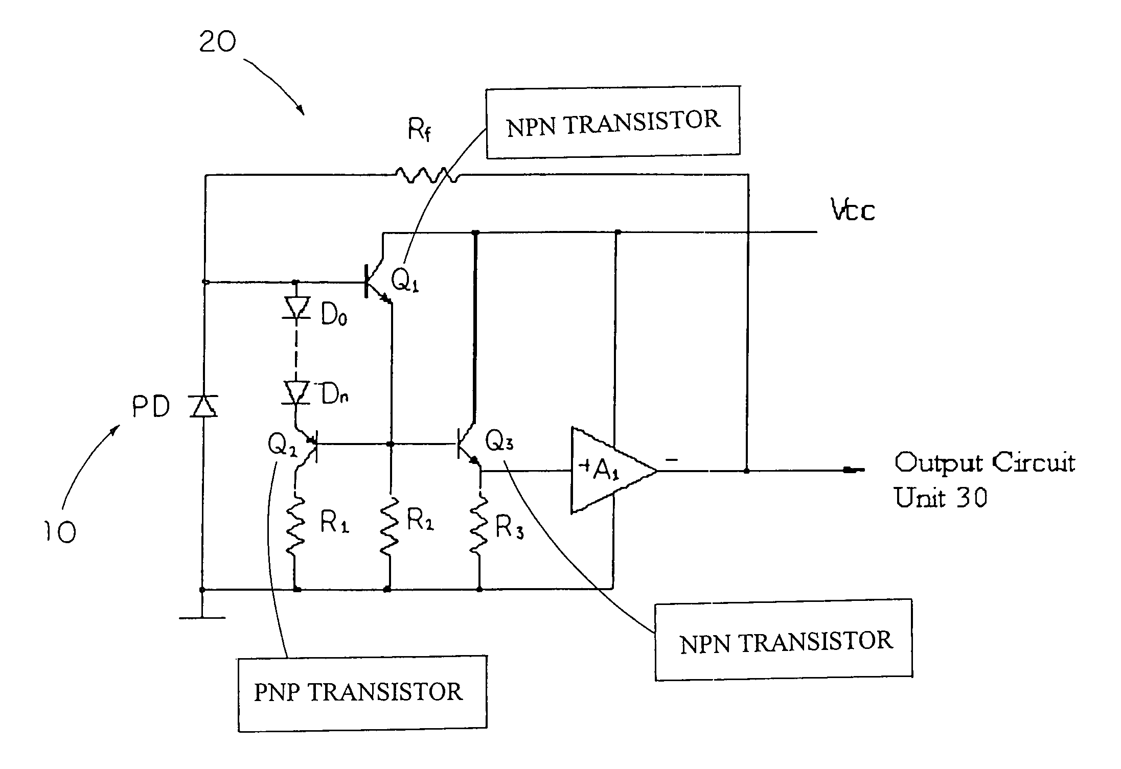
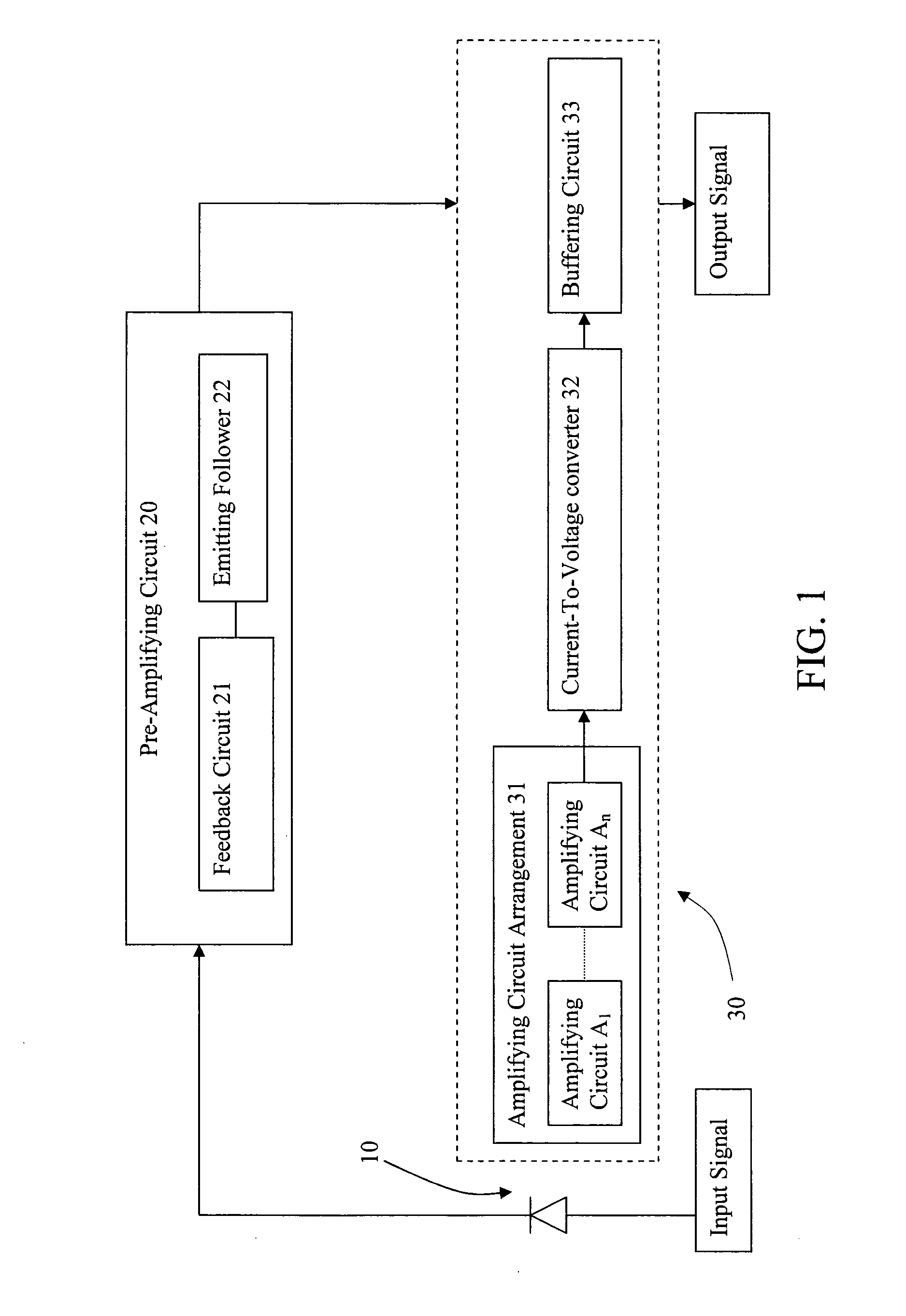
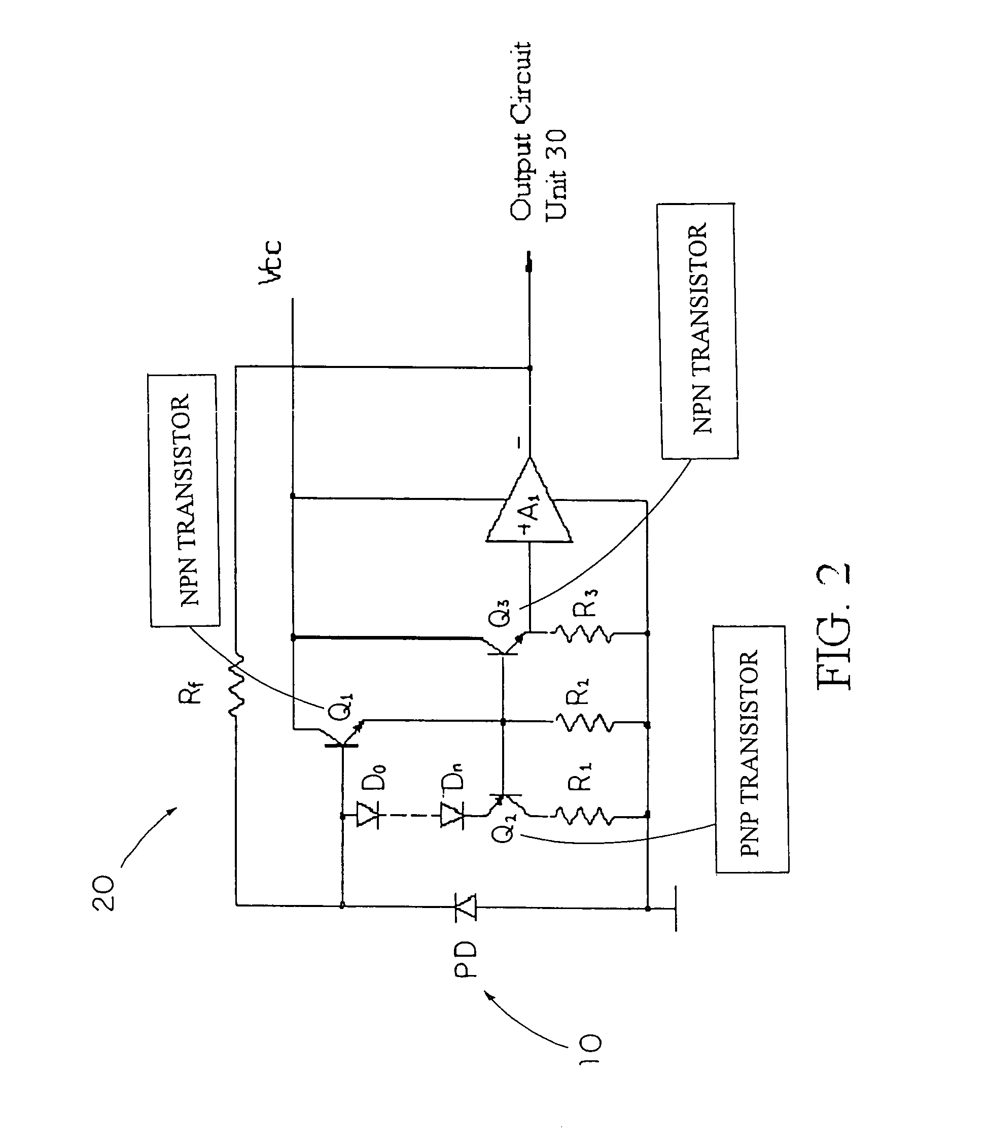
[0018]Referring to FIG. 1 of the drawings, an optical input preamplifier of an optical receiver according to a preferred embodiment according to a preferred embodiment of the present invention is illustrated, wherein the optical input preamplifier comprises a photodiode 10 for converting an input optical signal into a photocurrent as an output current, means 20 for pre-amplifying the output current from the photodiode 10, wherein the output current 30 is pre-amplified to form a pre-amplifying current and an output circuit unit 30.

[0019]According to the preferred embodiment, the photodiode 10, which is embodied as a kind of P-N junction specifically designed to optimize the inherent photosensitivity, is used for the detection of optical communication signals and for conversion of optical power to electrical power. Accordingly, when the photodiode 10 receives the input optical signal, the photodiode 10 converts the input optical signal into the output current in responsive to the phot...


PUM


Abstract

An optical input preamplifier includes a photodiode for converting an input optical signal into a photocurrent as an output current, pre-amplifying circuit for pre-amplifying the output current from the photodiode wherein the output current is pre-amplified to form a pre-amplifying current, and an output circuit device converting the pre-amplifying current into an output signal. Therefore, the output current from the photodiode passes through the pre-amplifying circuit and the output circuit unit to substantially enhance the sensitivity of the optical input preamplifier.

Description

BACKGROUND OF THE PRESENT INVENTION[0001]1. Field of Invention[0002]The present invention relates to a light-to-voltage converter, and more particularly to an optical input preamplifier of an optical receiver, which comprises a feedback circuit incorporating with a current-to-voltage converter for substantially reducing the impedance input thereof so as to enhance the sensitivity of the optical input preamplifier.[0003]2. Description of Related Arts[0004]Optical receivers are commonly used as a data transmission apparatus. A conventional optical receiver generally comprises a photodiode which receives an optical signal and outputs a photocurrent, and an optical input preamplifier for converting and amplifying an optical signal into an electrical signal. Accordingly, the optical input preamplifier is one of the major factors to determine the sensitivity of the optical receiver.[0005]Since the photocurrent is directly be converted and amplified into the electrical signal, the optical ...

Claims


Application Information

Patent Timeline
Patent Type & Authority Patents(United States)
IPC IPC(8): H03F3/08
CPCH03F3/087
Inventor YI, HEQING
Owner YI HEQING
Why Eureka
Try Eureka