This helps you quickly interpret patents by identifying the three key elements:
Problems solved by technology
Method used
Benefits of technology
Benefits of technology
[0020]It is an objective of the present invention to provide a keypad that is designed to be produced with less expense and to minimize the thickness thereof by integrating a thin film EL element thereinto.
[0021]It is another objective of the present invention to provide a keypad that can enhance the reliability and increase its life by preventing the noise and vibration generated by an EL element.
Problems solved by technology
Furthermore, since the key 50, the dome switch 68, and the printed circuit board 64 are disposed in the front housing of the mobile phone, and a part of the key 50 is exposed out of the front housing, it is time consuming to assemble all of the members, thereby deteriorating the productivity.
Furthermore, a dome switch, a moving contact point, and a fixed contact point that are constituting the luminous element are not sealed, this causes the mobile phone's life to be reduce and also causes a shielding process for preventing the noise and vibration caused by current applied to the luminous element to be required.
Method used
Image
Click on the blue label to locate the original text in one second.
Reading with bidirectional positioning of images and text.
Examples
first embodiment
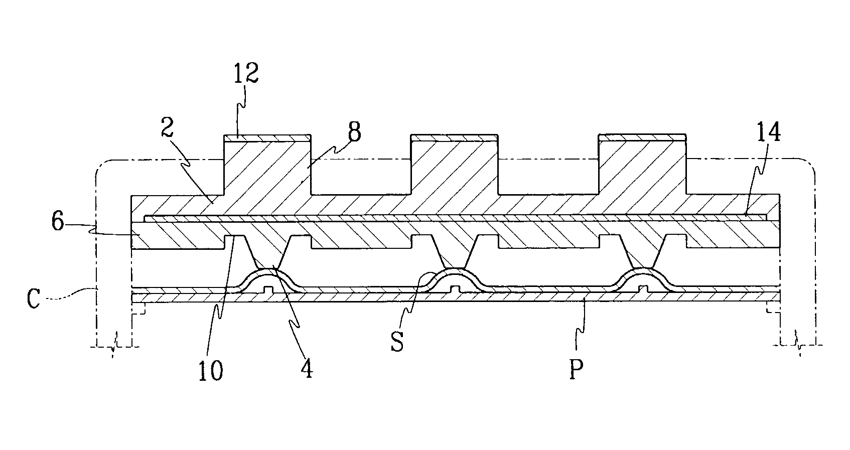
[0034]FIGS. 1 and 2 show a keypad according to the present invention. A keypad of this embodiment may be formed of silicon rubber.
[0035]A keypad of this embodiment comprises an upper pad member 2 having plural key tops 8 pressed or touched by a user and a base pad member 6 disposed opposing the upper pad member 2, and an EL element 14 integrally disposed between the upper and base pad members 2 and 6.
[0036]The key tops 8 of the upper pad member 2 are arranged to maintain their space at a predetermined distance and elevated upward passing over a front cover and spaced away from each other at a predetermined distance. The base pad member 6 is provided with plural projections 4 corresponding to the key tops 8.
[0037]The projections 4 are located such that they can press corresponding dome switch S provided on a circuit board P by the user pressing the key tops 8.
[0038]The base pad member 6 is further provided with groove portions 10 for providing the elastic force and the restitutive fo...
second embodiment
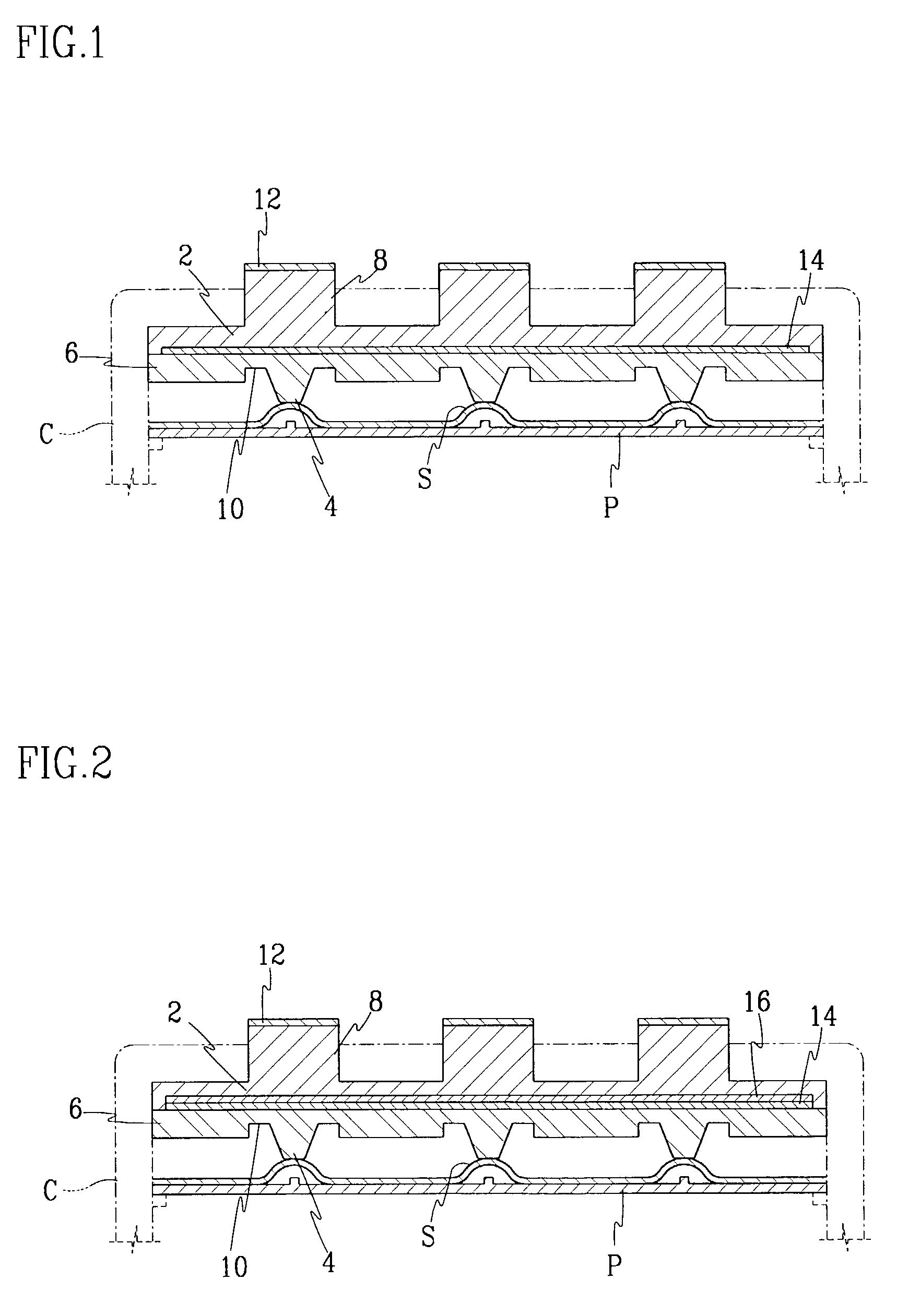
[0048]FIGS. 4 and 5 show the present invention.
[0049]The keypad of the second embodiment is identical to that of the first embodiment except that the key tops are formed of a different material from that of the pad members.
[0050]That is, the key pad of this second embodiment comprises a base pad member 6a formed of silicon rubber, an upper pad member 6b integrally formed with the base pad member 6a, and key tops 20 formed of synthetic resin, the key tops 20 being attached on the upper pad member 6b by adhesive 22.
[0051]In this embodiment, the EL element 14 is also surface-contacted with the pad members.
third embodiment
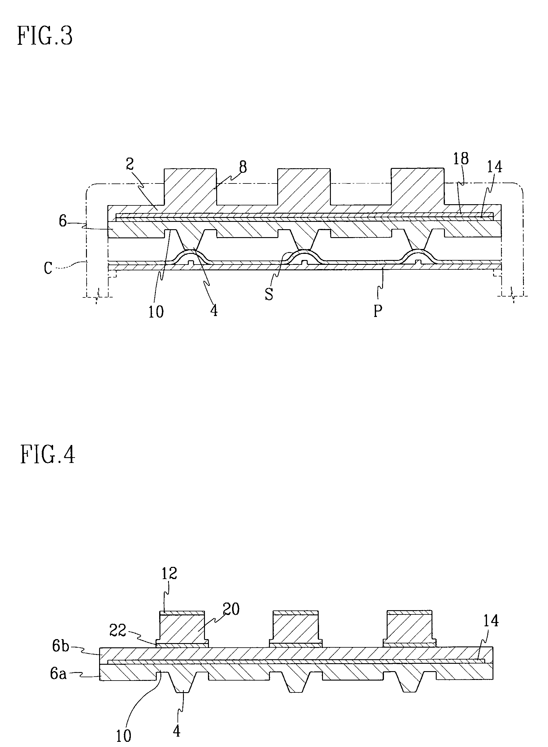
[0052]FIG. 6 shows a keypad according to the present invention.
[0053]In third embodiment, the EL element 14 having a length identical to that of a base pad member 6 formed of silicon rubber is integrally surface-contacted with the EL element 14. A key tops 20 formed of synthetic resin is attached on the EL element by adhesive 22.
[0054]As described above, as the thin EL element is integrally inserted into the keypad, the thickness of the keypad can be minimized while simplifying the assembling and manufacturing process, thereby improving the productivity.
[0055]In addition, since the EL element is tightly disposed contacting between the base and upper pad members, the noise and vibration caused by the EL element can be suppressed, thereby improving the reliability and endurance of the element.
PUM
Abstract
A keypad for a mobile phone includes a circuit board having a fixed contact point; a dome switch disposed on the circuit board; a base pad member having a projection for pressing the dome switch to generate signal; an upper pad member having a key top, the upper pad member being integrally formed with the base pad member, and an EL element disposed surface-contacting between the base pad member and the upper pad member.
Description
CROSS-REFERENCE TO RELATED APPLICATION[0001]This application claims priority of Korean Patent Application No. 2001-27898, filed on May 22, 2001.BACKGROUND OF THE INVENTION[0002](a) Field of the Invention[0003]The present invention relates to a keypad for a mobile phone and, more particularly, to a keypad that has a sheet-type luminous element (an EL element) formed in a thin sheet and integrated therein, thereby minimizing noise and vibration generated by the EL element.[0004](b) Description of the Related Art[0005]Generally, a keypad for a mobile phone is an input device consisting of a separate grid of numerical and function keys arranged for efficient data entry. The keys are fitted into holes formed on a front housing of the mobile phones and jutted out so that users can conveniently input the data.[0006]Light source formed of a luminous element is installed on the bottoms of the key so that the user can identify the numerical numbers and letters printed on the keys in a dark pl...
Claims
Application Information
Patent Timeline
Application Date:The date an application was filed.
Publication Date:The date a patent or application was officially published.
First Publication Date:The earliest publication date of a patent with the same application number.
Issue Date:Publication date of the patent grant document.
PCT Entry Date:The Entry date of PCT National Phase.
Estimated Expiry Date:The statutory expiry date of a patent right according to the Patent Law, and it is the longest term of protection that the patent right can achieve without the termination of the patent right due to other reasons(Term extension factor has been taken into account ).
Invalid Date:Actual expiry date is based on effective date or publication date of legal transaction data of invalid patent.

