Turbo-reception method and turbo-receiver

a technology which is applied in the field of turbo-receiver and receiver, can solve the problems of preventing an equalization in the equalizer, poor channel estimation accuracy, and affecting the transmission efficiency of intended data, so as to achieve good accuracy

Inactive Publication Date: 2006-04-11
NTT DOCOMO INC
View PDF6 Cites 78 Cited by
  • Summary
  • Abstract
  • Description
  • Claims
  • Application Information

AI Technical Summary

Benefits of technology

[0020]It is another object of the invention to provide a reception method and a receiver therefor in which a channel value of a received signal is estimated from the received signal and a known signal serving as a reference signal, the received signal is processed using the esti...

Problems solved by technology

Up to the present time, a study of a specific implementation of an MIMO receiver in an MIMO system is not yet satisfactorily warranted.
A poor accuracy of the channel estimation prevents an equalization in the equalizer 21 from occurring in a proper manner.
The accuracy ...

Method used


Image

  • Turbo-reception method and turbo-receiver
  • Turbo-reception method and turbo-receiver
  • Turbo-reception method and turbo-receiver

Examples


Embodiment Construction

First Aspect of the Invention (1)

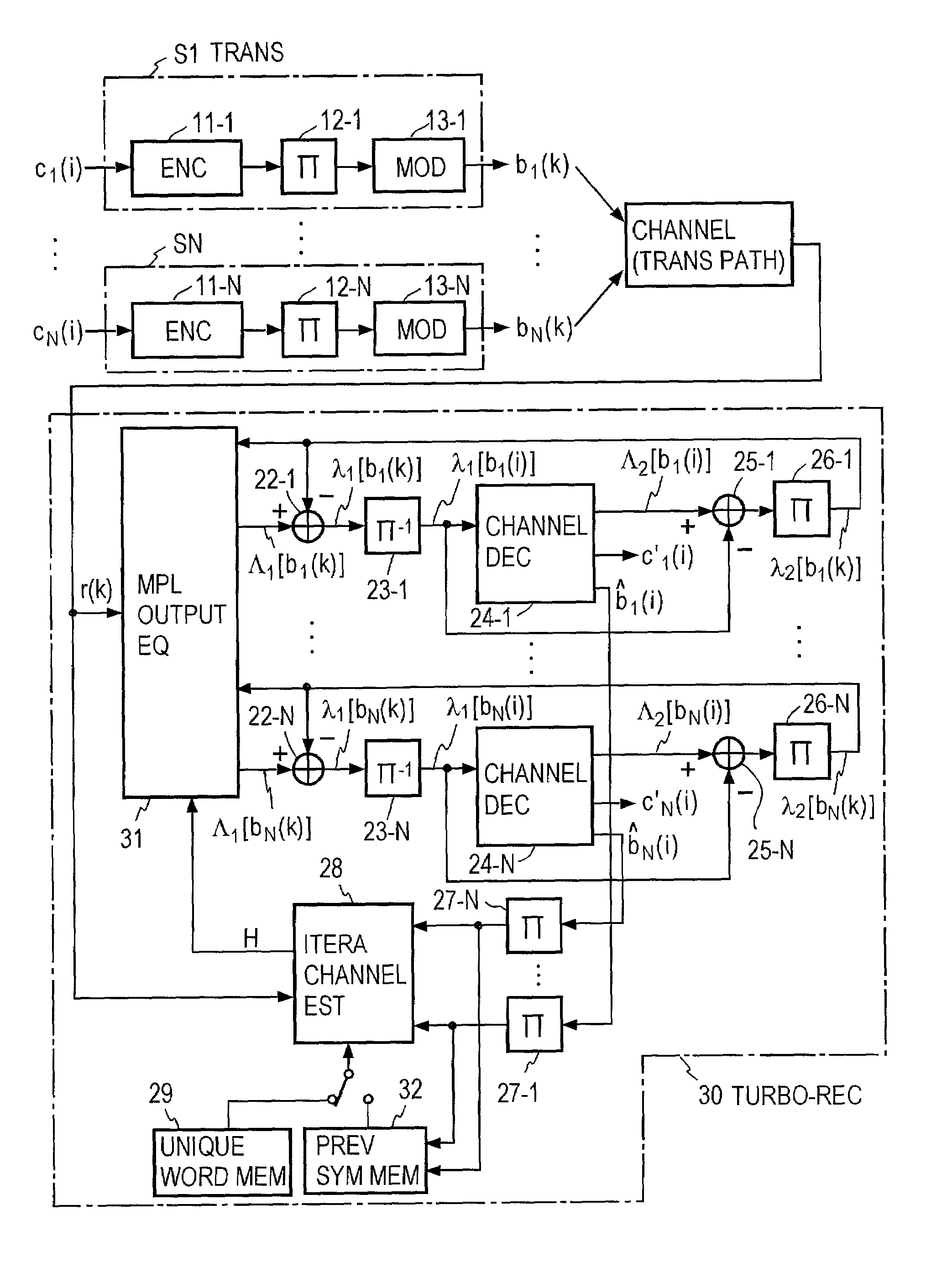
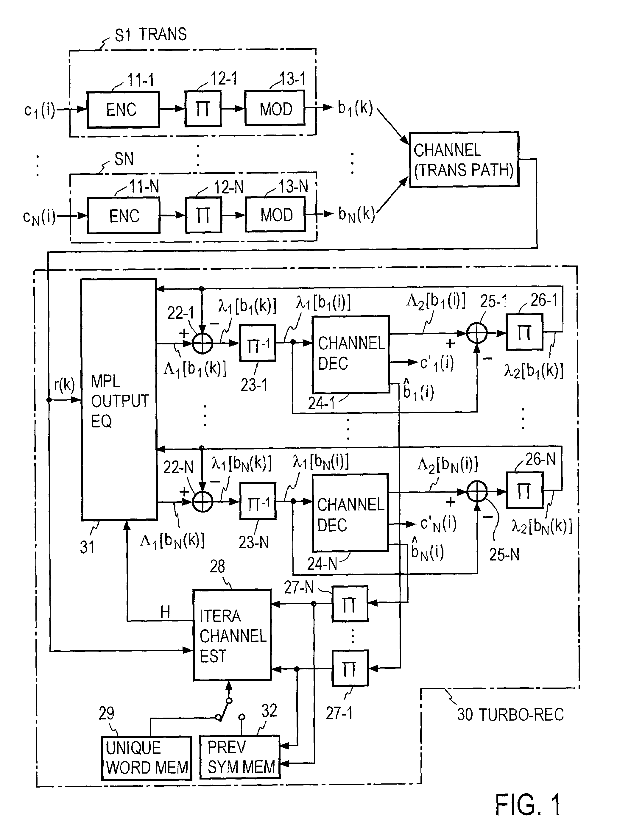
[0063]FIG. 1 shows an exemplary arrangement of an MIMO system to which the present invention is applied.

[0064]In each of N transmitters S1 . . . SN, information series c1(i) to cN(i) are encoded in encoders 11-1, . . . , 11-N, and the encoded outputs are fed through interleavers 12-1, . . . , 12-N to modulators 13-1, . . . , 13-N as modulation signals, thus modulating a carrier signal in accordance with these modulation signals to transmit signals b1(k) to bN(k). In this manner, transmitted signals b1(k) . . . bN(k) from the transmitters S1, . . . , SN form N series transmitted signals.

[0065]A received signal r(k) which is received by a multiple output receiver through transmission paths (channels) is input to a multiple output equalizer 31. A signal received by the receiver is converted into a baseband signal, which is then sampled at one-half the symbol period, for example, to be converted into a digital signal, which is then input to the equalizer...


PUM


Abstract

An impluse response hmn(q) of each transmission path is estimated from N received signals rm (m=1, . . . , M) and a known signal (for a number of users equal to N, n=1, . . . , N). M×N matrix H (q) having hmn(q) as an element and a Q×Q matrix H having H(q) as an element are determined (where Q represents a number of multipaths of each transmitted wave and q=0, . . . , Q−1). A soft decision value b′n(k) is determined from decoded λ2 [bn(k)], and this is used to generate an interference component matrix B′(k) to generate an interference replica H·B′(k). The interference replica H·B′(k) is subtracted from a received matrix y(k) to determine y′(k). y(k) and H are used to determine an adaptive filter coefficient wn(k) to be applied to an n-th user in order to eliminate residual interference components in y′(k) according to the minimum mean square error criteria. y(k) is passed through wn(k) to provide a log-likelihood ratio as a received signal from the user n from which interferences are eliminated.

Description

BACKGROUND OF THE INVENTION[0001]The invention relates to turbo-reception method and a turbo-receiver as may be used in a mobile communication, for example, and which apply an iterative equalization utilizing a turbo-coding technique to waveform distortions which result from interferences.[0002]A task in the mobile station communication business is how to construct a system capable of acquiring a multitude of users on a limited frequency domain with a high quality. A multi-input multi-output (MIMO) system is known in the art as means for solving such a task. The architecture of this system is shown in FIG. 30A where a plurality of transmitters S1 to SN transmit symbols c1(i) to cN(i) at the same time and on the same frequency, and the transmitted signals are received by an MIMO receiver equipped with a plurality of antennas #1 to #M. The received signals are processed by the receiver, which estimates transmitted symbols c1(i) to cN(i) from the respective transmitters S1 to SN and de...

Claims


Application Information

Patent Timeline
IPC IPC(8): H04L27/06H03M13/03H03M13/29H04B1/7115H04B3/06H04B7/005H04J13/00H04L1/00H04L25/02
CPCH04L1/005H04L25/0236H04L25/0204
Inventor ABE, TETSUSHIFUJII, HIROMASATOMISATO, SHIGERUMATSUMOTO, TADASHI
Owner NTT DOCOMO INC
Why Eureka
Try Eureka