Single-ended loop test circuitry in a central office DSL modem

a test circuit and central office technology, applied in the field of data communication, can solve the problems of one-half of the transmitted power of the signal being dissipated by such passive termination, poor snr of some subchannels, and inability to use bidirectional communication techniques in dsl “training” and other problems, to achieve the effect of accurate measurement of loop parameters

Active Publication Date: 2006-04-11
TEXAS INSTR INC
View PDF5 Cites 20 Cited by
  • Summary
  • Abstract
  • Description
  • Claims
  • Application Information

AI Technical Summary

Benefits of technology

[0038]It is therefore an object of this invention to provide a modem transceiver that include

Problems solved by technology

Typically, the SNR of some subchannels is so poor that these subchannels are unloaded, carrying no bits.
Because there is necessarily no DSL transceiver located at the customer premises prior to installation, the bidirectional communications techniques used in DSL “training” are not available.
However, one-half the transmitted power of the signal is dissipated by such passive termination.
While this impedance measurement SELT approach is accurate for short transmission loops, it has been observed that this method is not particularly useful for longer transmission loops.
It is therefore difficult to estimate the termination impedance from the determination of the overall loop impedance ZL.
This makes measurement of the loop impedance ZL difficult when active t

Method used


Image

  • Single-ended loop test circuitry in a central office DSL modem
  • Single-ended loop test circuitry in a central office DSL modem
  • Single-ended loop test circuitry in a central office DSL modem

Examples


Embodiment Construction

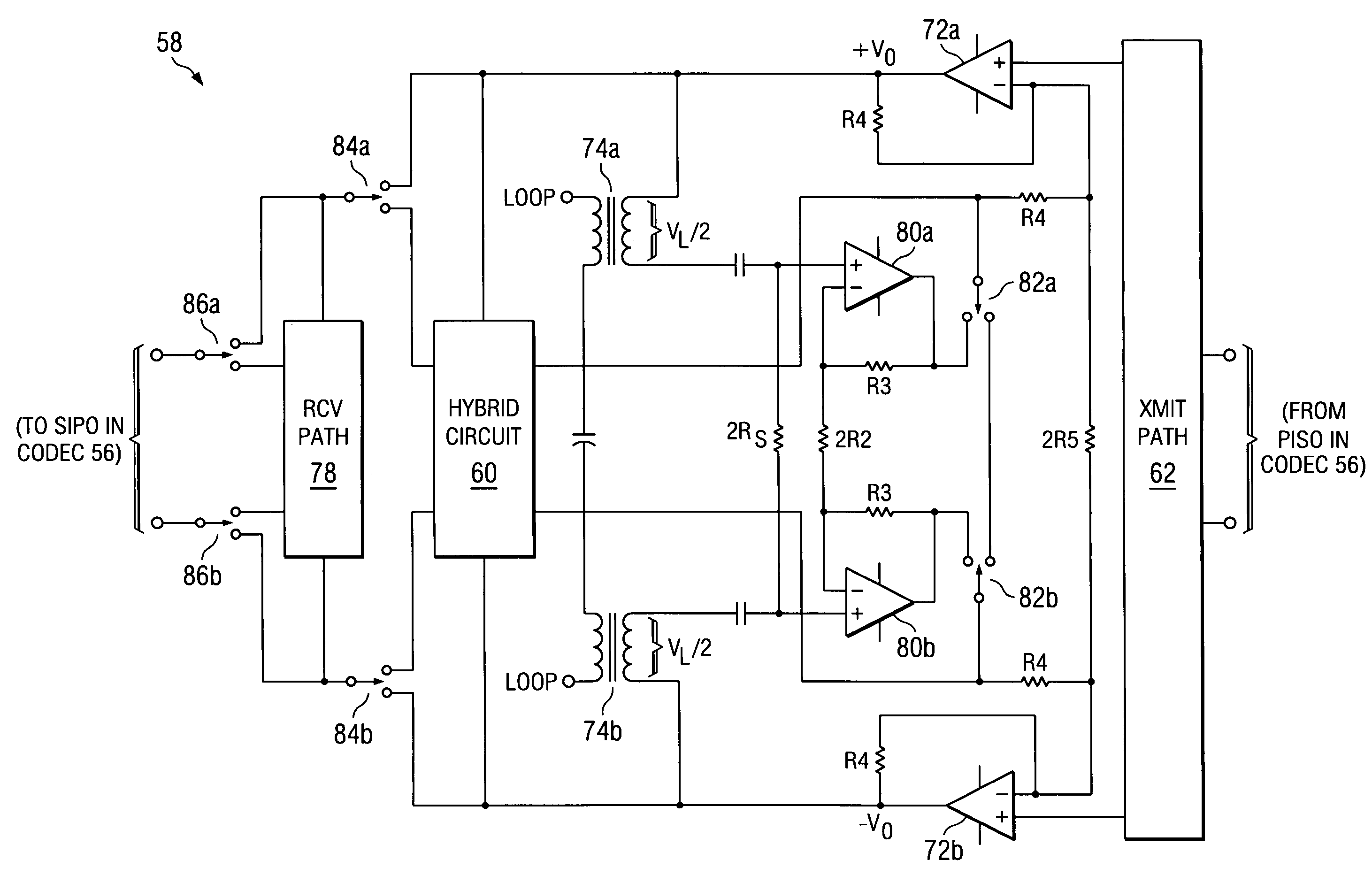
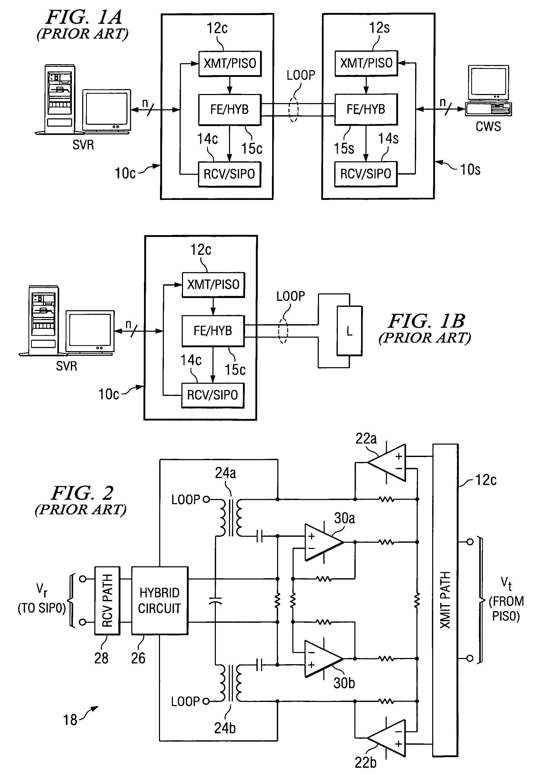
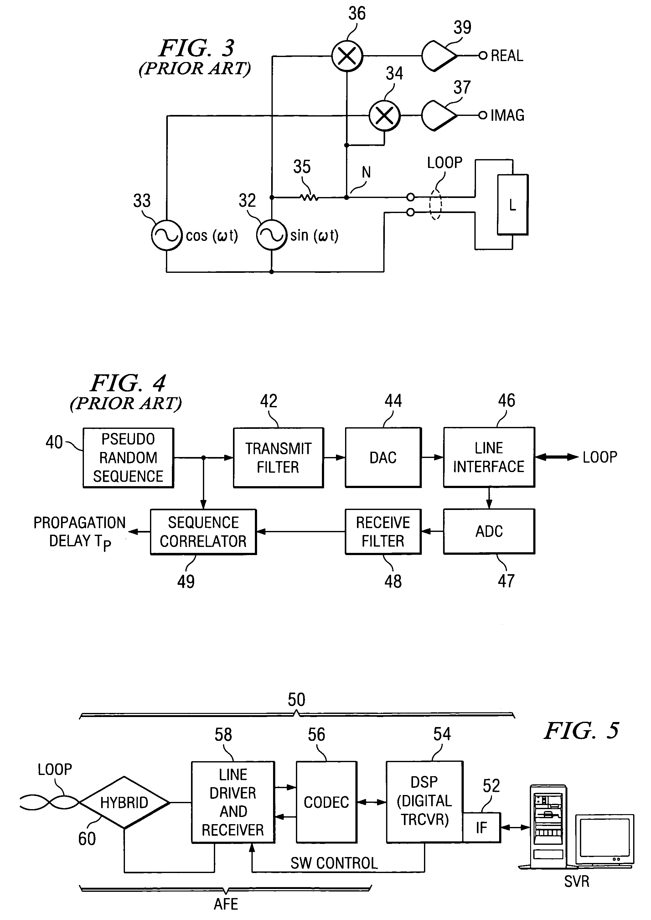
[0060]The present invention will be described in connection with its preferred embodiments, in a central office (CO) Digital Subscriber Line (DSL) modem transceiver. This example of the implementation of this invention is considered to be especially appropriate for this description, as it is believed that the advantages of this invention are of great benefit to such an implementation. In this example, the DSL modem in this example carries out Discrete Multitone modulation of signals, based on the inverse FFT (IFFT) of data symbols, because of the popularity of this technology for ADSL communications. However, this invention is it is contemplated that this invention may also be used in other applications and implementations including, for example, according to other modulation techniques as used for other types of DSL and broadband communications, and the benefits of this invention attained at least in part in such other applications and implementations. Accordingly, the following de...


PUM


Abstract

A central office modem (50) that includes the capability of single-ended loop testing (SELT) is disclosed. The modem (50) includes a digital signal processor (54), a codec (56), line driver and receiver circuitry (58), and a hybrid circuit (60), by way of which a subscriber loop (LOOP) can be driven and sensed. The line driver and receiver circuitry (58) may include a transformer (74a, 74b) for driving the loop (LOOP), or the output may be capacitively coupled. The line driver and receiver circuitry (58) includes active termination, by way of operational amplifiers (80a, 80b). Switches (82a, 82b; 84a, 84b) are provided to selectively enable and disable the active termination function, and to selectively bypass or include the hybrid circuit (60). This control of the line driver and receiver circuitry (58) provides the ability to calibrate out its own characteristics, providing high precision SELT measurements of the load impedance type, and of frequency domain reflectometry, and time domain reflectometry. A third set of switches (86a, 86b) selectively bypass receive path filter circuitry (78), to permit upstream and downstream noise measurements.

Description

CROSS-REFERENCE TO RELATED APPLICATIONS[0001]Not applicable.STATEMENT REGARDING FEDERALLY SPONSORED RESEARCH OR DEVELOPMENT[0002]Not applicable.BACKGROUND OF THE INVENTION[0003]This invention is in the field of data communications, and is more specifically directed to measurement of subscriber loop parameters from a central office location for Digital Subscriber Line (DSL) communications.[0004]High-speed Internet access is now a widespread utility for many businesses, schools, and homes. As is fundamental in this art and as well known by most consumers, broadband communications according to Digital Subscriber Line (DSL) is a popular technology for providing high-speed communications over existing telephone lines, without disturbing conventional voice telephony (Plain Old Telephone Service, or “POTS”).[0005]FIG. 1a illustrates a conventional subscriber loop carrying out DSL communications between server SVR at a central office (CO) and a subscriber workstation CWS at the client premi...

Claims


Application Information

Patent Timeline
IPC IPC(8): H04M1/00H04M9/00H04B3/46H04M3/30
CPCH04B3/46H04M3/30H04M3/305H04M3/2209
Inventor SHI, HAOMELSA, PETER J.
Owner TEXAS INSTR INC
Why Eureka
Try Eureka