Optical fiber and optical fiber sensors

a technology of optical fiber and optical fiber sensors, applied in the field of optical fibers and to optical fiber sensors, can solve the problems of the dual sensitivity of fbg sensors to strain (s) and temperature (t), and the difficulty of independent measurement of these two measures

Inactive Publication Date: 2006-04-11
THE HONG KONG POLYTECHNIC UNIV
View PDF13 Cites 44 Cited by
  • Summary
  • Abstract
  • Description
  • Claims
  • Application Information

AI Technical Summary

Problems solved by technology

One of the most significant limitations of FBG sensors is their dual sensitivity to both strain (S) and temperature (T).
This leads to difficulty in the independent measurement of these two measurands.

Method used


Image

  • Optical fiber and optical fiber sensors
  • Optical fiber and optical fiber sensors
  • Optical fiber and optical fiber sensors

Examples


Embodiment Construction

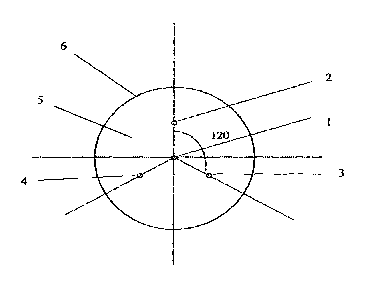
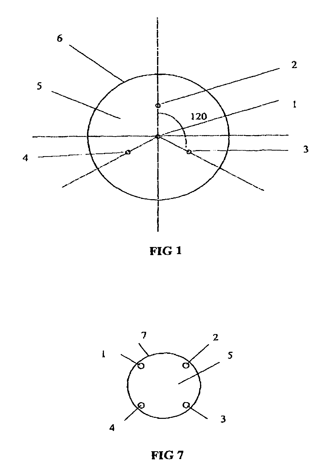
[0051]Referring to FIG. 1, in a first embodiment of the invention a polymeric optical fiber 6 comprises four light guiding cores 1, 2, 3 and 4 located in a common cladding 5. The first core 1 lies in the center of the cladding 5. The other three cores 2, 3 and 4 lie at 120 degrees intervals equidistant from first core 1. The distances between the cores 1, 2, 3 and 4 is large enough to avoid any mode coupling between them.

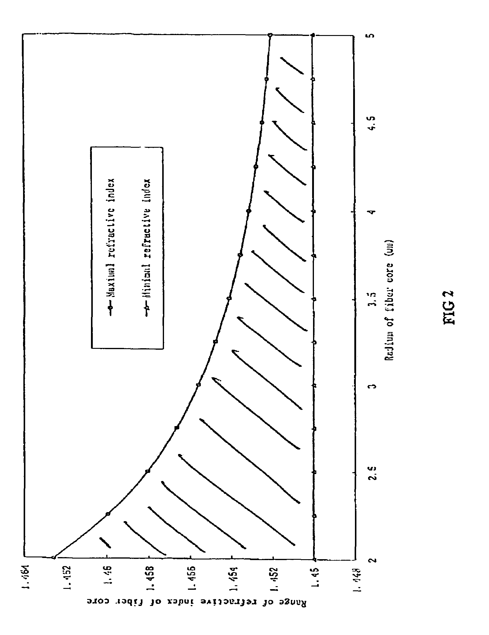
[0052]The refractive indexes of the cores 1, 2, 3 and 4 are larger than the refractive index of the cladding 5, but smaller than the value which depends on the single mode operation. Typically, the core radium of single-mode fibers is about 3.5×10⁻⁴ inches or 9 microns in diameter. FIG. 2 is a graph of a range of refractive indexes for single mode fiber cores in a cladding with a refractive index of 1.45. For single mode operation the refractive index of a core must lie in the shaded region of the graph between the curves. According to FIG. 2, a large increase in th...


PUM

PropertyMeasurementUnit
refractive indexaaaaaaaaaa

Abstract

An optical fiber device has at least two cores within the same cladding having different characteristics. The characteristics include including strain optic coefficient, thermo-optic coefficient, thermal expansion coefficient, photo-sensitivity and refractive index. One or more cores can have a Bragg grating.

Description

BACKGROUND TO THE INVENTION[0001]1. Field of the Invention[0002]The invention relates to optical fibers and to optical fiber sensors. The invention also relates to fabrication methods for optical fibers and to coupling methods.[0003]2. Background Information[0004]Fiber-optic technologies offering both sensing and signal transmission functions have attracted considerable attention in recent years, especially in smart concrete structures including highways, bridges, dams and buildings. Also, since optical fiber Bragg grating (FBG) sensors are of small size and light weight compared to textile yarns, and are readily embedded or ever woven inside textiles, they are the most promising sensor for smart textiles.[0005]Optical fiber Bragg grating sensor comprises an optical fiber with a grating formed transversely across it by exposing the fiber to UV irradiation. The grating produces a differing refractive index within the core of the optical fiber. When light wave propagates along the cor...

Claims


Application Information

Patent Timeline
Patent Type & Authority Patents(United States)
IPC IPC(8): G02B6/02G02B6/34B29D11/00G02B6/42G02B27/09
CPCB29D11/00721G02B6/02033G02B6/02042G02B27/0966G02B6/02114G02B6/4206G02B27/0911G02B6/021C03B2203/34
Inventor TAO, XIAOMINGYU, JIANMINGYANG, DONGXIAO
Owner THE HONG KONG POLYTECHNIC UNIV
Why Eureka
Try Eureka