
Method and apparatus for affecting atrial defibrillation with bi-atrial pacing

a bi-atrial pacemaker and atrial fibrillation technology, applied in the direction of heart stimulators, heart defibrillators, therapy, etc., can solve the problems of shortened life of the defibrillator, patient discomfort, and reduced quality of life, so as to reduce the risk of atrial fibrillation and the recurrence of atrial fibrillation

Inactive Publication Date: 2006-04-11
MEDTRONIC INC
View PDF31 Cites 64 Cited by
  • Summary
  • Abstract
  • Description
  • Claims
  • Application Information

AI Technical Summary

Benefits of technology

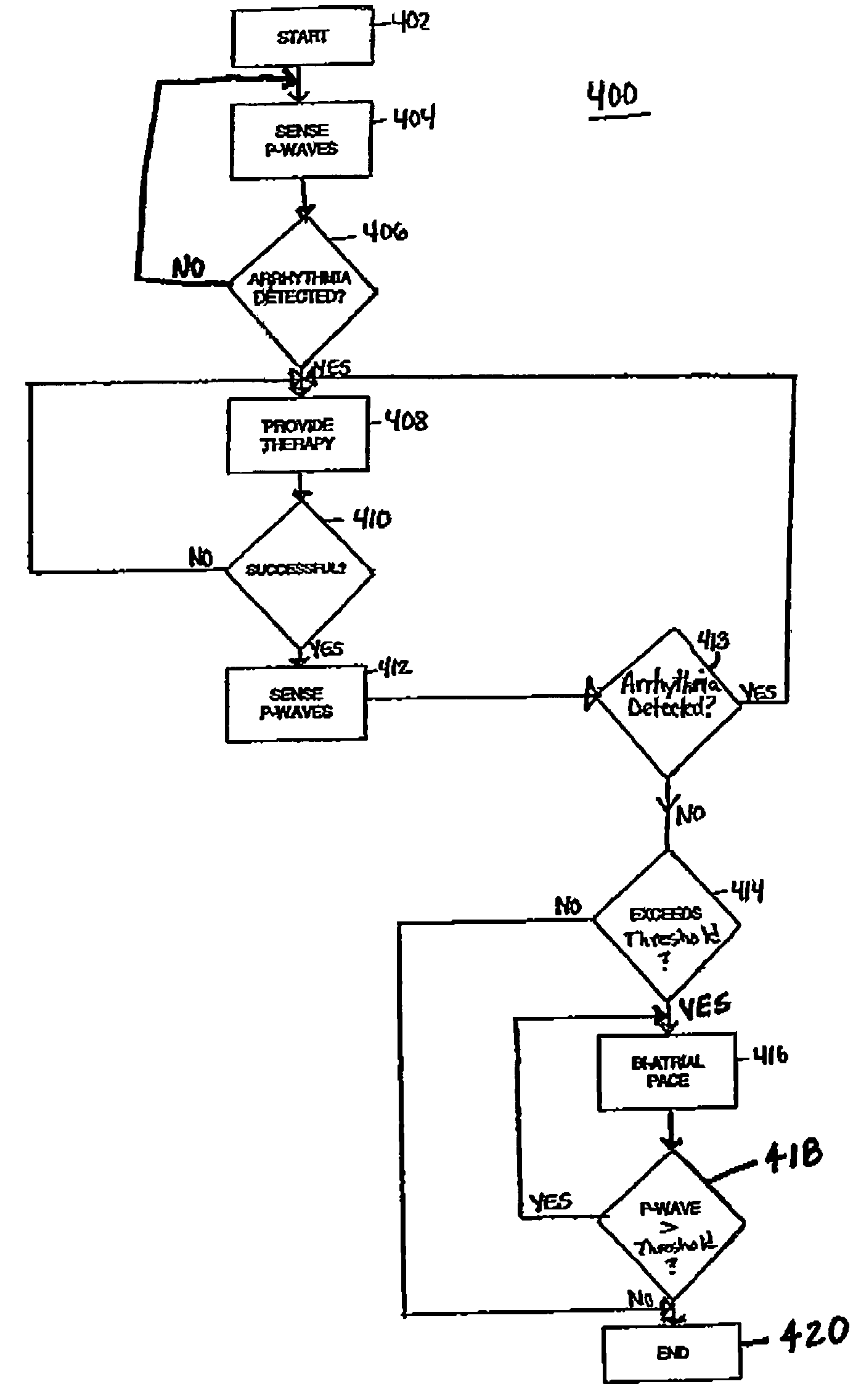
[0009]The present invention is directed toward the provision of an entirely endocardial defibrillation lead system particularly optimized for use in defibrillation or cardioversion of the atrium. The system disclosed includes coronary sinus, right atrial, and right ventricular electrodes, and may be embodied with the electrodes located on the same or different lead bodies. Additionally, bi-atrial pacing is incorporated to prevent the reoccurrence or re-initiation of atrial fibrillation after a successful cardioversion or defibrillation therapy.
[0010]According to the present invention, an implantable medical device for delivering a first therapy in response to variations in heart rhythm detected by electrodes inserted within a patient includes an amplifier generating p-waves in response to a signal between the electrodes, and a pacer timing/control circuit. In response to the first therapy being successful, the pacer timing/co...

Problems solved by technology

In many patients, upon successful termination of atrial fibrillation by cardioversion and / or defibrillation, the immediate or near immediate reoccurrence of atrial fibrillation is a known problem.
If multiple re-initiations occurred, this would cause multiple fibrillation detections and treatments causing shortened defibrillator life, patient discomfort, and reduced quality of life.

Method used


Image

  • Method and apparatus for affecting atrial defibrillation with bi-atrial pacing
  • Method and apparatus for affecting atrial defibrillation with bi-atrial pacing
  • Method and apparatus for affecting atrial defibrillation with bi-atrial pacing

Examples


Embodiment Construction

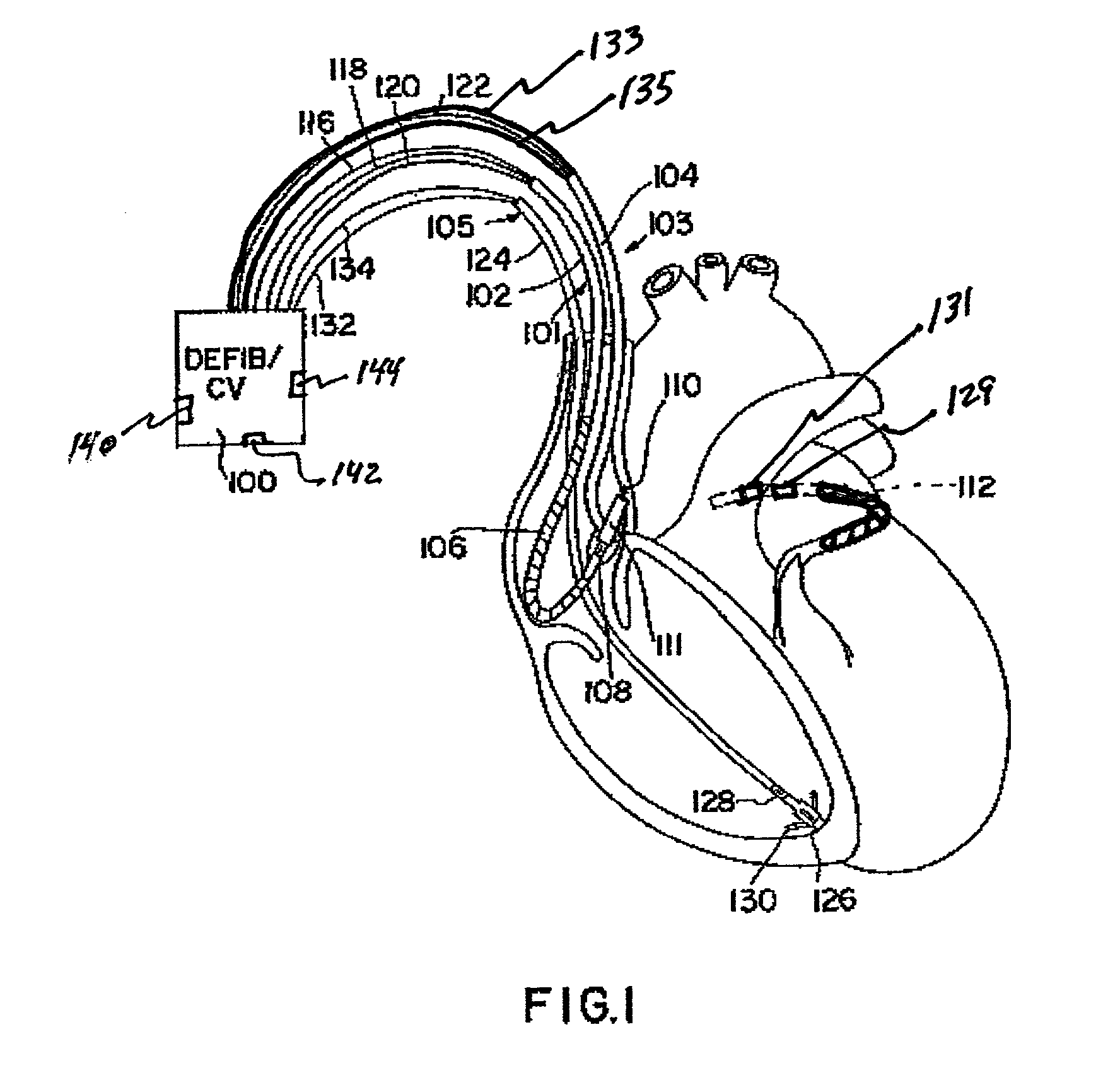
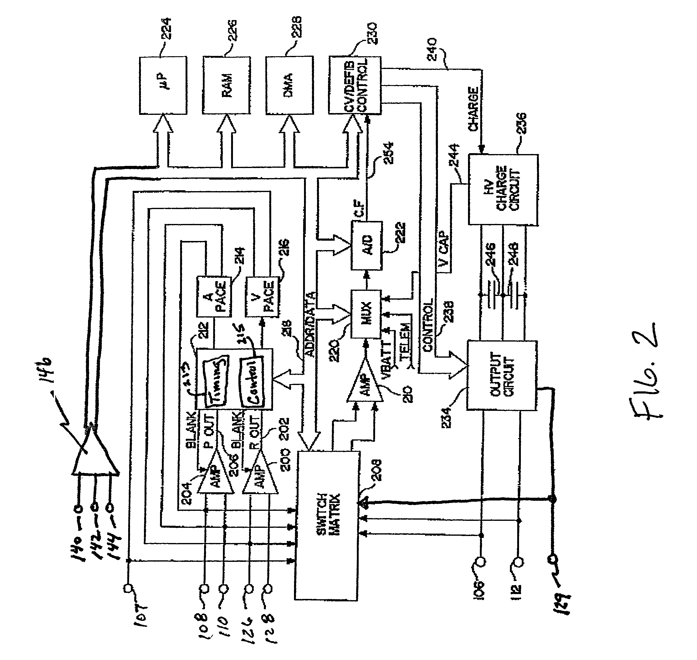
[0018]FIG. 1 is a cutaway view of the human heart in which a lead system suitable for use in practicing the present invention has been implanted. The lead system includes three leads. A right atrial lead 101 includes an elongated insulative lead body 102, to which a coiled defibrillation electrode 106 has been mounted. The distal end of the lead includes an electrode head 111, carrying a helical electrode 110 and a ring electrode 108. The electrodes 106, 108 and 110 are coupled to an implantable pacemaker / cardioverter / defibrillator 100 by means of conductors 116, 118 and 120. Electrodes 108 and 110 are employed for cardiac pacing and sensing in the atrium.

[0019]A coronary sinus lead 103 also has an elongated insulative lead body 104 which carries a coiled defibrillation electrode at its distal end, located as generally indicated at 112. Electrode 112 is located within the coronary sinus and the great cardiac vein. Preferably the proximal end of the electrode 112 is spaced about 3 to...


PUM


Abstract

A method and apparatus for cardioverting the atrium of a human heart that includes insertion of first and second elongated electrodes tranvenously into the heart and associated vessels. One electrode is preferably located in the coronary sinus and great vein of the heart. The other electrode is preferably located in the vicinity of the right atrium of the heart, spaced from the electrode located in the coronary sinus. In response to detection of fibrillation or in response to manual triggering, a defibrillation pulse is applied between the first and second electrodes to effect atrial cardioversion. Further, after delivery of a successful defibrillation shock, the width of intrinsic p-waves are monitored and bi-atrial pacing is temporarily initiated if the width exceeds a preset or programmable threshold.

Description

BACKGROUND OF THE INVENTION[0001]The present invention relates to implantable cardioverters / defibrillators generally, and more particularly to an implantable bi-atrial pacemaker / defibrillator with capability of atrial fibrillation reoccurrence prevention.[0002]Early concepts of implantable defibrillators, such as those disclosed in Reissue Pat. No. 27,652 by Mirowski, et al, envision an electrode system employing a ventricular endocardial electrode and a plate electrode mounted to the heart directly, subcutaneously, or to the skin. However, it has long been recognized that a totally transvenous system would be desirable in order to simply the use of implantable defibrillators. One such system is suggested in Mirowski, et al U.S. Pat. No. 3,942,536, which discloses a transvenous lead having electrodes intended for location in the right ventricular apex and in the superior vena cava. This electrode system is disclosed as useful for either ventricular or atrial defibrillation.[0003]Whi...

Claims


Application Information

Patent Timeline
IPC IPC(8): A61N1/362A61N1/368A61N1/39
CPCA61N1/3962A61N1/3684A61N1/395A61N1/39622A61N1/36843A61N1/36842
Inventor THOMPSON, DAVID L.
Owner MEDTRONIC INC
Learn More