
Methods for determining formation and borehole parameters using fresnel volume tomography

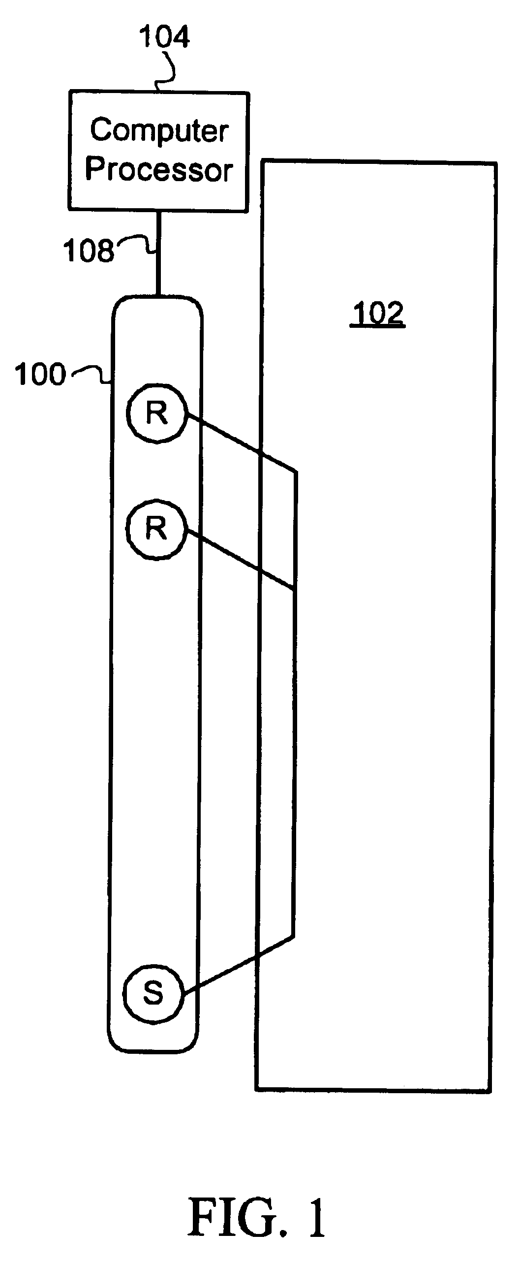
a technology of volume tomography and fesnel, which is applied in the direction of seismology for waterlogging, using reradiation, instruments, etc., can solve the problems of infrequent use of hornby's method, inaccuracy of estimation, and wrong final solution

Inactive Publication Date: 2006-04-11
SCHLUMBERGER TECH CORP
View PDF2 Cites 34 Cited by
  • Summary
  • Abstract
  • Description
  • Claims
  • Application Information

AI Technical Summary

Benefits of technology

[0013]Additional advantages and novel features of the invention will be set forth in the description which follows or may be learned by those skilled in the art through reading these materials or practicing the invention. The advantages of the invention may be achieved through the means recited in the attached claims.

Problems solved by technology

This estimate, however, is subject to inaccuracies due to tool tilt, borehole washouts, bed boundary effects, etc.
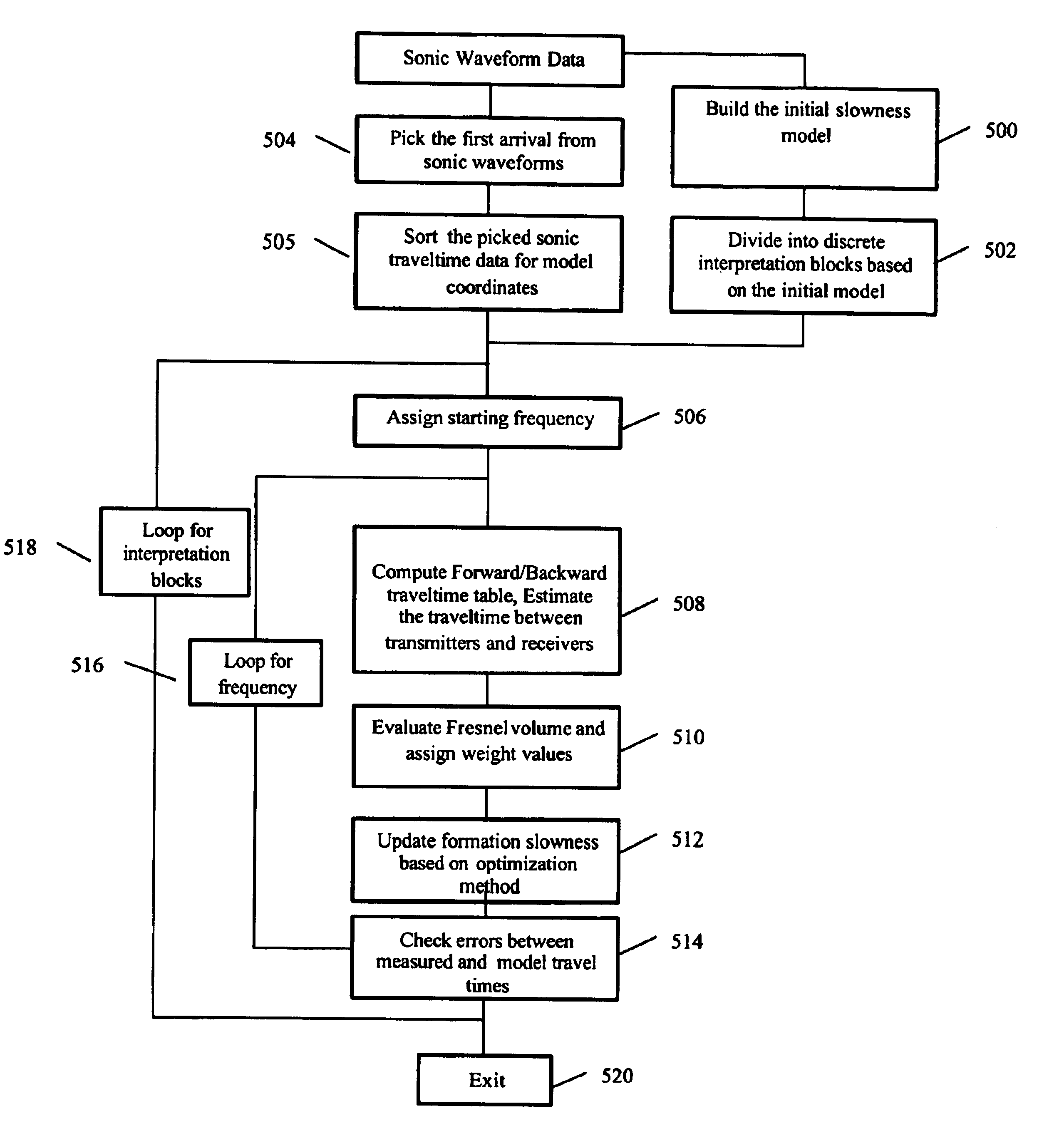
However, since the model used is unlikely to be the true subsurface model, the calculated travel times are typically not consistent with the actual measured travel times. Hence, followed by this “forward modeling” step, the discrepancy between the actual measured and the calculated travel times is calculated and then minimized by an optimization / minimization method (e.g. a back-projection or conjugate-gradient) to update / adjust the previous resultant model.
It can be easily understood that an inaccurate and less robust modeling will generate incorrect travel times hence result in a wrong final solution.
The method disclosed by Hornby, however, is not in frequent use, presumably because the modeling kernel based on a ray tracing technique for refraction waves is unreliable.
In addition, the Hornby method requires implicitly imposed virtual layers along the borehole axis, which lacks robustness regarding prior information and geological support.
Furthermore, the method taught by Hornby is limited to only two dimensions, i.e. along borehole axis and one of the radial directions.
Although ray tracing is a well know numerical simulation technique and widely used in acoustic domain for travel time computations, there are numerous limitations of this method preventing its robust use for sonic tomography.
Actual waves, however, frequently are band-limited.
For sonic waves, where the wavelength is not vastly smaller than the distance between a source and receivers, such a ray approximation is not accurate enough.
Further, ray tracing computation is expensive, unstable and practically difficult to apply to a three-dimensional (3-D) tomography.

Method used


Image

  • Methods for determining formation and borehole parameters using fresnel volume tomography
  • Methods for determining formation and borehole parameters using fresnel volume tomography
  • Methods for determining formation and borehole parameters using fresnel volume tomography

Examples


case 1

General The point to be computed has six neighbors, two in each direction

[0052]First, the spatial forward and backward derivative operators are defined as: Dijk-r=Tijk-Ti-1,j,kΔ⁢ ⁢r, ⁢Dijk+r=T1+i,j,k-TijkΔ⁢ ⁢rDijk-θ=Tijk-Ti,j-1,kr⁢ ⁢Δ⁢ ⁢θ, ⁢Dijk+θ=Ti,j+1,k-Tijkr⁢ ⁢Δ⁢ ⁢θDijk-z=Tijk-Ti,j,k-1Δ⁢ ⁢z, ⁢Dijk+z=Ti,j,k+1-TijkΔ⁢ ⁢z

Thus, the eikonal equation can be approximated by the following formula: max⁡(Dijk-r,-Dijk+r,0)2+max⁡(Dijk-θ,-Dijk+θ,0)2+ max⁡(Dijk-z,-Dijk+z,0)2=sijk2(9)

[0053]In one given direction, if the two neighbors have already been computed, the one with the minimum value will appear in the eikonal equation approximation. If only one neighbor is known, the other one is infinite, and thus, only the known value will appear in the eikonal equation approximation. If neither of the neighbors has been computed, they have both an infinite value, and thus, the corresponding term will disappear in the eikonal equation approximation.

case 1a

nt at least in each direction has already been computed

[0054]To solve this equation, the following notations are chosen:

Tmin,l=min(Ti−1,j,k;Ti+1,j,k)

Tmin,j=min(Ti,j−1,k;Ti,j+1,k)

Tmin,k=min(Ti,j,k,−1;Ti,j,k+1)

Thus, the eikonal equation can be written: (Tijk-Tmin,IΔ⁢ ⁢r)2+(Tijk-Tmin,Jr⁢ ⁢Δθ)2+(Tijk-Tmin,JΔ⁢ ⁢z)2=sijk2(10)

Which leads to the quadratic equation (11): Tijk2⁡(1Δ⁢ ⁢r2+1r2⁢Δ⁢ ⁢θ2+1Δ⁢ ⁢z2)-2⁢Tijk⁡(Tmin,IΔ⁢ ⁢r2+Tmin,Jr2⁢Δ⁢ ⁢θ2+Tmin,KΔ⁢ ⁢z2)+Tmin,I2Δ⁢ ⁢r2+Tmin,J2r2⁢Δ⁢ ⁢θ2+Tmin,K2Δ⁢ ⁢z2-sijk2=0

and we have: Δ=4r2⁢Δ⁢ ⁢r2⁢Δ⁢ ⁢θ2⁢Δ⁢ ⁢z2⁡[sijk2⁡(r2⁢Δ⁢ ⁢θ2⁢Δ⁢ ⁢z2+Δ⁢ ⁢r2⁢Δ⁢ ⁢z2+r2⁢Δ⁢ ⁢r2⁢Δ⁢ ⁢θ2)]-4r2⁢Δ⁢ ⁢r2⁢Δ⁢ ⁢θ2⁢Δ⁢ ⁢z2⁢(r2⁢Δ⁢ ⁢θ2⁡[Tmin,I-Tmin,J]2+Δ⁢ ⁢r2⁡[Tmin,J-Tmin,K]2+Δ⁢ ⁢z2⁡[Tmin,I-Tmin,J]2)

[0055]Taking the solution that yields a traveltime greater than the ones already computed: Tijk=1r2⁢Δ⁢ ⁢θ2⁢Δ⁢ ⁢z2+Δ⁢ ⁢r2⁢Δ⁢ ⁢z2+r2⁢Δ⁢ ⁢r2⁢Δ⁢ ⁢θ2[ ⁢(r2⁢Δ⁢ ⁢θ2⁢Δ⁢ ⁢z2⁢Tmin,I+ Δ⁢ ⁢r2⁢Δ⁢ ⁢z2⁢Tmin,J+r2⁢Δ⁢ ⁢r2⁢Δ⁢ ⁢θ2⁢Tmin,K)+ r⁢ ⁢Δ⁢ ⁢r⁢ ⁢Δθ⁢ ⁢Δ⁢ ⁢z[sijk2⁡(r2⁢Δ⁢ ⁢θ2⁢Δ⁢ ⁢z2+Δ⁢ ⁢r2⁢Δ⁢ ⁢z2+r2⁢Δ⁢ ⁢r2⁢Δ⁢ ⁢...

case 1b

direction, the two neighboring points are unknown

[0056]In one direction with two neighboring points unknown, we have only two minimums that will appear in the approximation of the eikonal equation. Identifying the two minimums T1and T2, Δ1 and Δ2 are the corresponding grid spacings (grid spacing in the direction were at least one neighbor has already been computed. The approximation of the eikonal equation is thus the following: (Tijk-T1Δ1)2+(Tijk-T2Δ2)2=sijk2

This leads to the quadratic equation: Tijk2⁡[1Δ12+1Δ22]-2⁢Tijk⁡[T1Δ12+T2Δ22]+T12Δ12+T22Δ22-sijk2=0Δ=4Δ12⁢Δ22⁡[sijk2⁡(Δ12+Δ22)-(T1-T2)2]

And hence Tijk=T1⁢Δ22+T2⁢Δ12Δ12+Δ22+Δ1⁢Δ2Δ12+Δ22⁢sijk2⁡(Δ12+Δ22)-(T1-T2)2(13)


PUM


Abstract

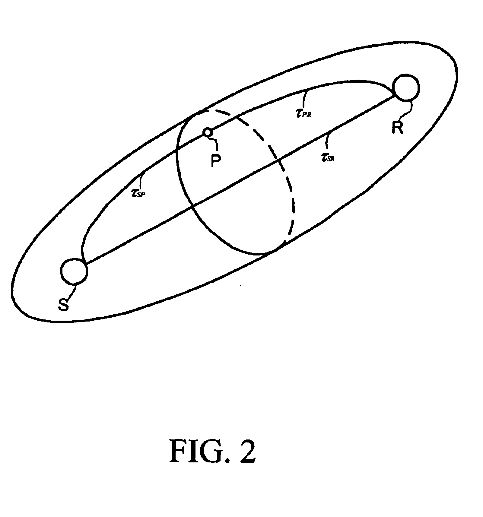
A method and apparatus for determining formation slowness around a borehole are provided. The Fresnel volume concept is applied for traveltime tomography. The Fresnel volume represents a sonic wave propagation path about the borehole. The application of Fresnel volume to sonic data provides for a stable inversion and makes practical 3-D tomography. Inversion is accomplished by an iterative back-projection method.

Description

FIELD OF THE INVENTION[0001]The present invention relates generally to methods for investigating subsurface formations using sonic measurements made in a borehole. More particularly, this invention is directed to methods for determining formation slowness along and around a borehole.BACKGROUND OF THE INVENTION[0002]The generation and recording of borehole acoustic waves is a key measurement employed in oilfield wireline logging. Many borehole tools and methods are currently available for taking acoustic measurements. Some tools include a single source of sonic waves and two or more receivers; however, most of the tools now include many receivers arranged in an array. While the currently available acoustic tools are useful in providing a large range of information regarding the adjacent formation and the borehole parameters, a primary use of acoustic borehole measurements is the estimation of compressional wave formation slowness.[0003]Compressional wave formation slowness is typical...

Claims


Application Information

Patent Timeline
IPC IPC(8): G01V1/48
CPCG01V1/48
Inventor MATSUOKA, TOSHIFUMIENDO, TAKESHICAO, DIBANCHET, NICHOLASLEE, JONGHA
Owner SCHLUMBERGER TECH CORP
Learn More