
Fast backprojection/reprojection with hexagonal segmentation of image

Inactive Publication Date: 2007-05-08
GENERAL ELECTRIC CO
View PDF6 Cites 59 Cited by
  • Summary
  • Abstract
  • Description
  • Claims
  • Application Information

AI Technical Summary

Benefits of technology

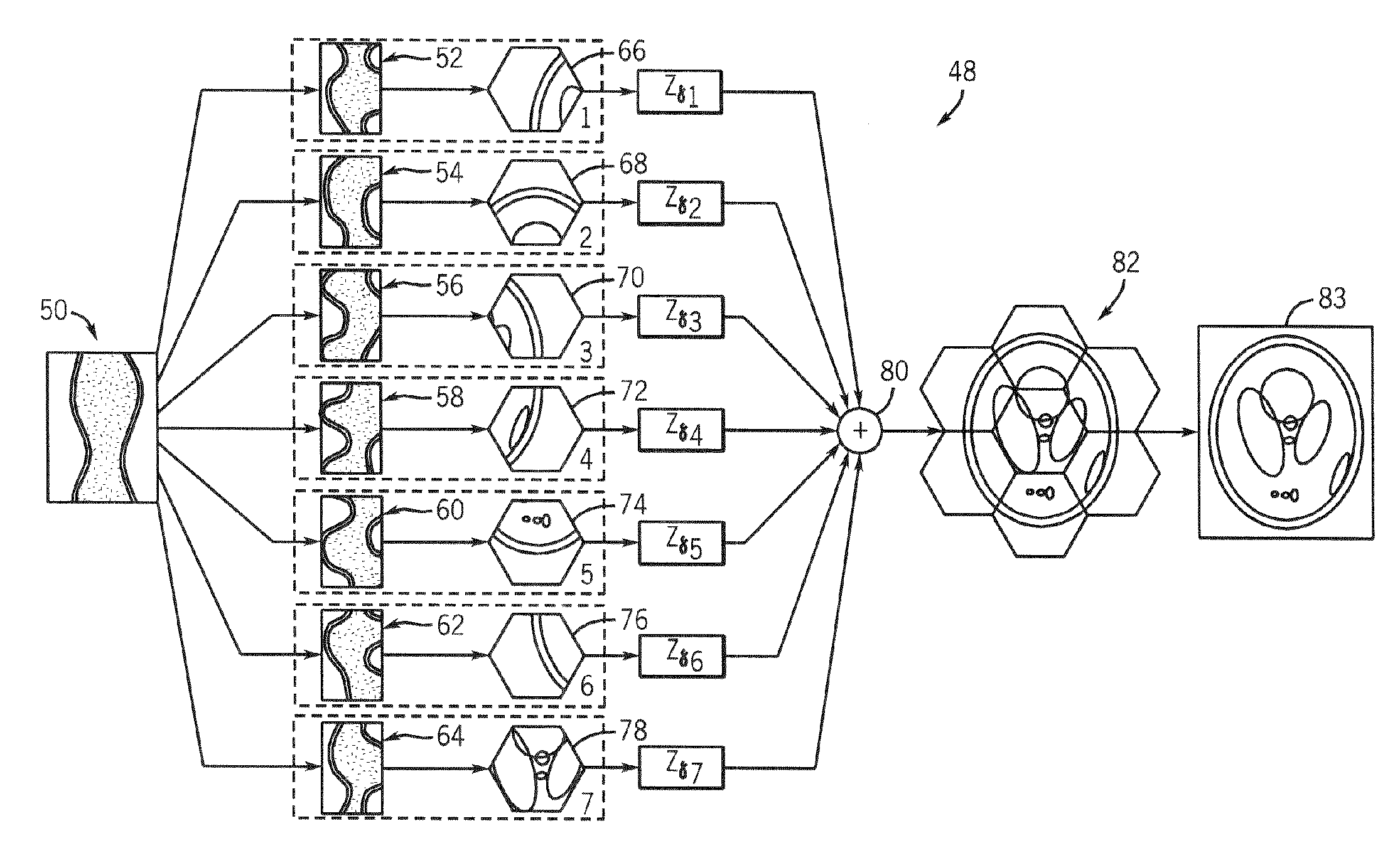
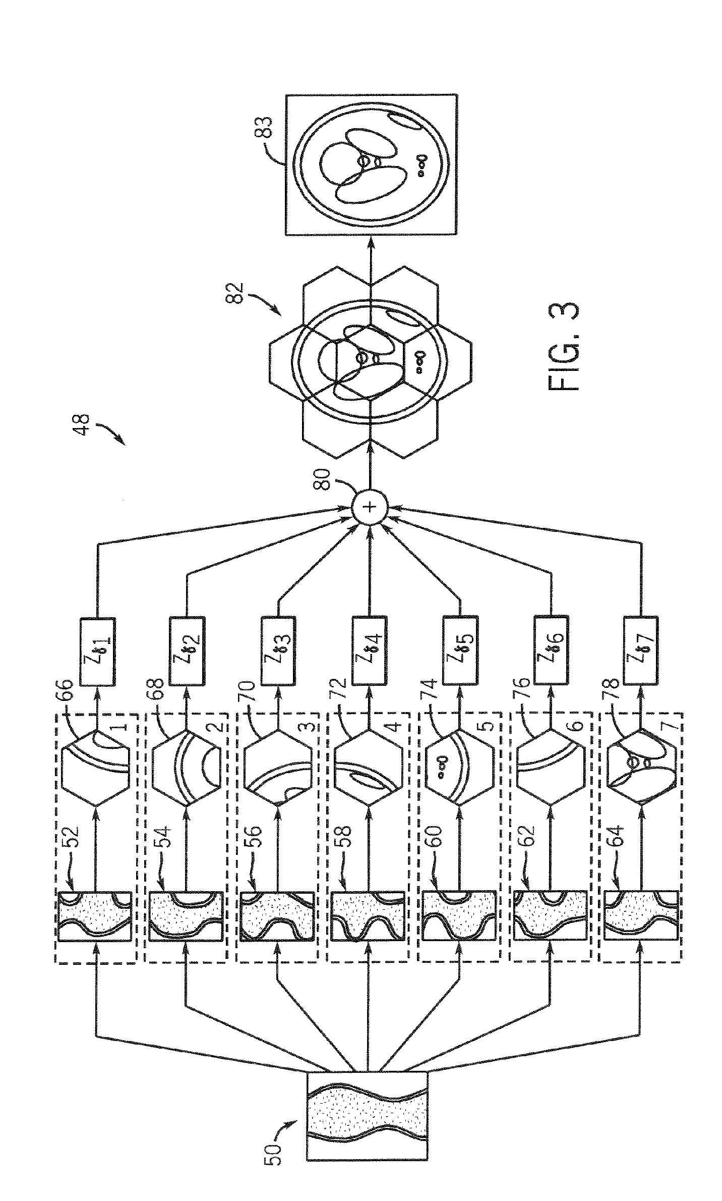
[0007]A reprojection/backprojection technique and apparatus for carrying out such a technique are disclosed. The technique provides a hierarchical solution to speeding-up reprojection and backprojection of tomographic images. In the context of reprojection, a tomographic image is divided into a series of hexagonal tiles. The image is divided into a series of subimages with each hexagonal subimage also tiled with hexagonal tiles. Each subimage is shifted to the origin, projected at a reduced number of views, interpolated to a larger number of projection angles via up-sampling, and then shifted back in the sinogram space (which corresponds to a view-by-view translation in the sinogram space). The resulting sinograms are then combined to provide a single sinogram. In the context of backprojection, the above steps are transposed such that a sinogram is divided into a series of subsinograms. Those subsinograms are then shifted view-by-view, smoothed and decimated

Problems solved by technology

However, notwithstanding these developments, the backprojection process has limited the ability to provide near real-time reconstruction of images.
As tomographic scanners are being designed to acquire the raw data at an increasingly faster rate, the computational requirements of conventional FBP becomes increasingly problematic and, as such, presents an obstacle to real-time imaging.
However, while the PBP process has been quickened, image quality and / or image accuracy has degraded.
While this proposed PBP technique reduces image reconstruction time, e.g., by a factor of N2log2N, the square pixels that the subsinograms represent result in less than ideal coverage of a circular field-of-view (FOV).
Furthermore, as is appreciated by those skilled in the art, square pixel grids do not provide the optimal sampling in the frequency domain for images, which tend to have a spherical support.
This suboptimal sampling can also reduce image quality.

Method used


Image

  • Fast backprojection/reprojection with hexagonal segmentation of image
  • Fast backprojection/reprojection with hexagonal segmentation of image
  • Fast backprojection/reprojection with hexagonal segmentation of image

Examples


Embodiment Construction

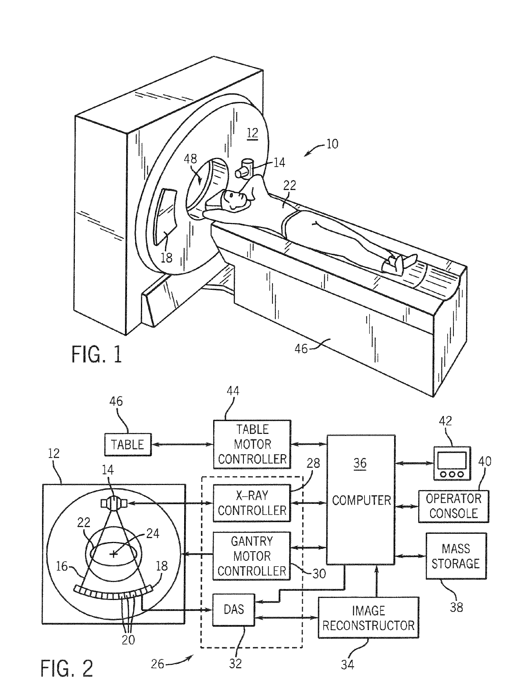
[0018]While embodiments of the invention are applicable to a number of tomographic systems, the operating environment of embodiments of the invention described herein will be described with respect to a CT system. While a “third generation” CT scanner will be particularly described, the invention is not so limited. Moreover, it is understood that the invention is also applicable with PET, MRI, SPECT, EIT, and optical tomography systems.

[0019]Referring to FIGS. 1 and 2, a computed tomography (CT) imaging system 10 is shown as including a gantry 12 representative of a “third generation” CT scanner. Gantry 12 has an x-ray source 14 that projects a beam of x-rays 16 toward a detector array 18 on the opposite side of the gantry 12. Detector array 18 is formed by a plurality of detectors 20 which together sense the projected x-rays that pass through a medical patient 22. Each detector 20 produces an electrical signal that represents the intensity of an impinging x-ray beam and hence the a...


PUM


Abstract

A reprojection / backprojection technique and apparatus for carrying out such a technique provides a hierarchical solution to speeding-up reprojection and backprojection of tomographic images. In the context of reprojection, a tomographic image is divided into a series of subimages. Each subimage is shifted to the origin, projected at a reduced number of views, and then up-sampled and shifted back (in the sinogram space). The resulting sinograms are then combined to provide a single sinogram. This process is applied one or more times recursively. In the context of backprojection, the above steps are transposed such that a sinogram is divided into a series of subsinograms. The subsinograms are then shifted and decimated by a given decimation factor. The decimated subsinograms are then backprojected onto hexagonal tiles whereupon the tiles are composited into a final image.

Description

BACKGROUND OF THE INVENTION[0001]The present invention relates generally to tomographic imaging and, more particularly, to reprojection and backprojection of tomographic images with hexagonal segmentation. The invention is applicable with tomographic imaging systems such as those used for medical imaging as well as those used for package / baggage security screening systems, non-destructive evaluation, or any other application domain requiring projection or backprojection.[0002]A number of imaging modalities, such as computed tomography (CT), positron emission tomography (PET), single photon counting tomography (SPECT), electrical impedance tomography (EIT), optical tomography, and certain acquisition methods for magnetic resonance imaging (MRI) utilize tomographic reconstruction techniques. Generally, in tomographic reconstruction, tomographic images are created from line or plane integral measurements of an object at a number of orientations. These integral measurements are then pro...

Claims


Application Information

Patent Timeline
IPC IPC(8): A61B6/03
CPCG06T11/006G06T2211/421Y10S378/901
Inventor BASU, SAMIT KUMARDEMAN, BRUNO KRISTIAAN BERNARD
Owner GENERAL ELECTRIC CO
Learn More