Rotary cutting unit

a cutting unit and rotary cutting technology, applied in the field of circular cutting units, can solve the problems of high disadvantage, high cost, complex and time-consuming, etc., and achieve the effects of reducing conversion time, increasing production output of cutting units, and increasing availability

Inactive Publication Date: 2006-04-18
ELPATRONIC AG
View PDF17 Cites 8 Cited by
  • Summary
  • Abstract
  • Description
  • Claims
  • Application Information

AI Technical Summary

Benefits of technology

[0013]Yet another advantage of the invention is the increased availability and increased production output of the cutting unit due to the reduced conversion time, rapid exchange of worn cutter units, simple dismantling of worn parts because the blade shafts are not continuous, and the possibility of exchanging the worn parts and grinding the circular blades outside the cutting equipment.
[0014]Still another advantage of the invention is the increased production output due to the cutting unit which is serviced more easily and quickly.
[0015]Another advantage of the present invention is realized by the non-interlocking upper blade drive in each circular cutting unit which allows easy and quick exchange of circular blades with minimal operational interruptions.
[0016]A further advantage of the present invention is a constant, burr-free cut-edge quality which is obtained by using a constant cutting gap, reduced overlap of the circular blades, and strongly reduced shearing surface.
[0017]A still further advantage of the present invention is realized by the cutting unit frame which carries the pressure between the two blades and thereby reduces shaft loads and allows a small shaft diameter and circular blade diameter. The result is a steeper cutting angle, lower forces, and a neater cut edge.

Problems solved by technology

Obviously such a procedure is both complex and time-consuming and, moreover, may lead to inaccuracies while there always is the danger of damage to the blades.
As a result, the cutting apparatus and hence the material being cut is contaminated with oil, and this feature is highly disadvantageous when making cans.
Another drawback of equipment of the state of the art is the large size of the cutting-disk shafts which is required.
Hence, such shafts are expensive and furthermore sensitive to thermal expansion.
Because the shaft diameters are large, the blade diameters also must be large, and as a result the blades evince an unfavorable, fairly shallow angle of cutting and hence generate untidy cut edges.

Method used


Image

  • Rotary cutting unit
  • Rotary cutting unit
  • Rotary cutting unit

Examples


Embodiment Construction

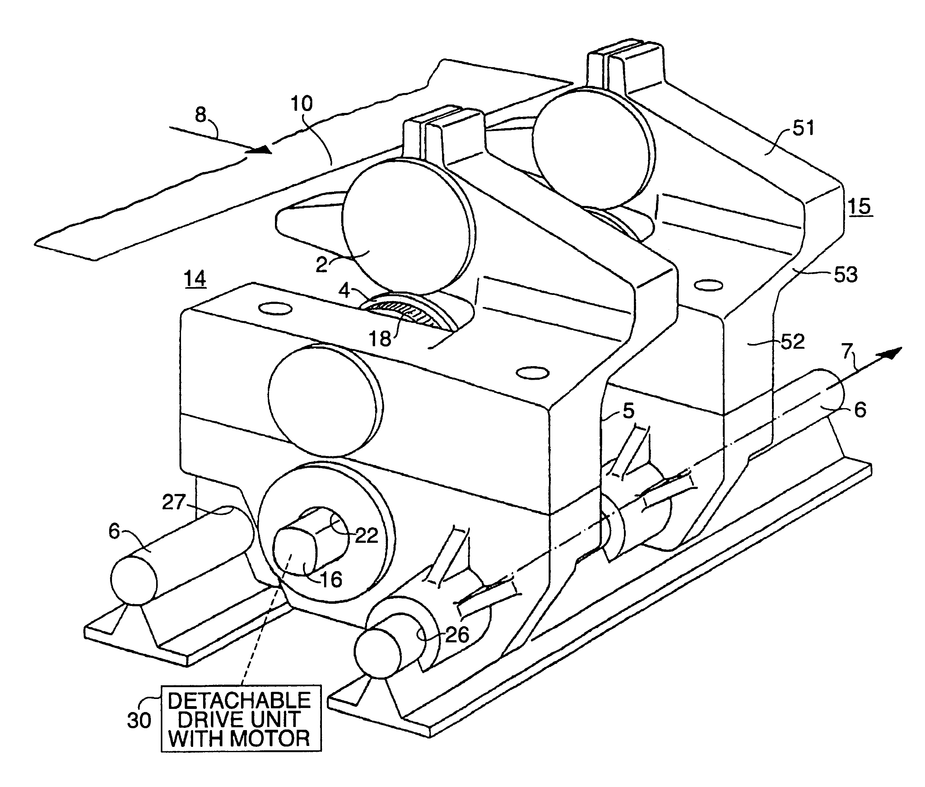
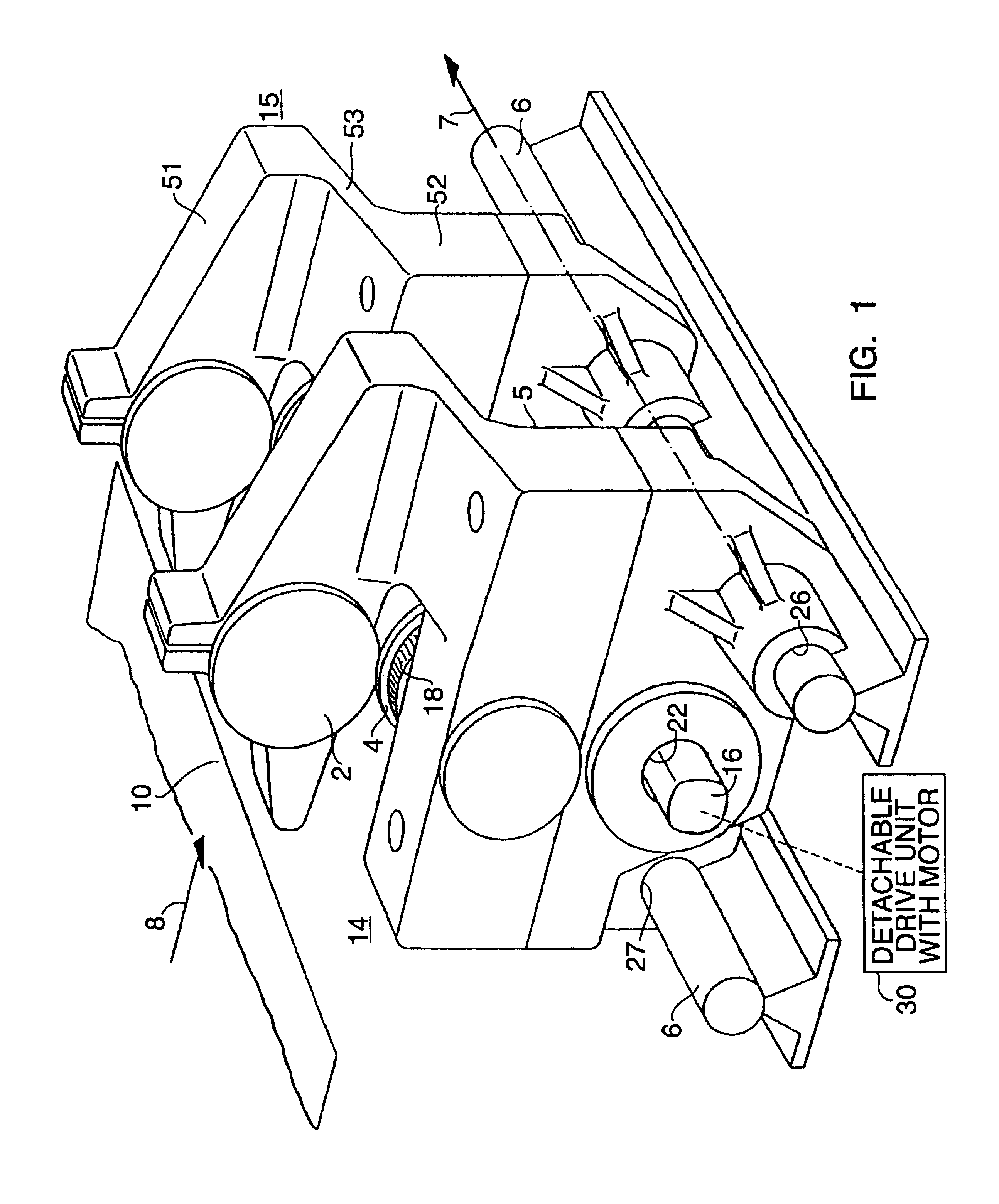
[0025]The circular cutter unit of the invention shown in FIGS. 1 through 4 essentially comprises an upper circular blade 2 and a lower circular blade 4, both operating perpendicularly to the horizontal plane 10 and in the longitudinal direction 8, that is, in the plane and direction of advance of the flat length of material being introduced, for instance sheet metal for manufacturing cans.

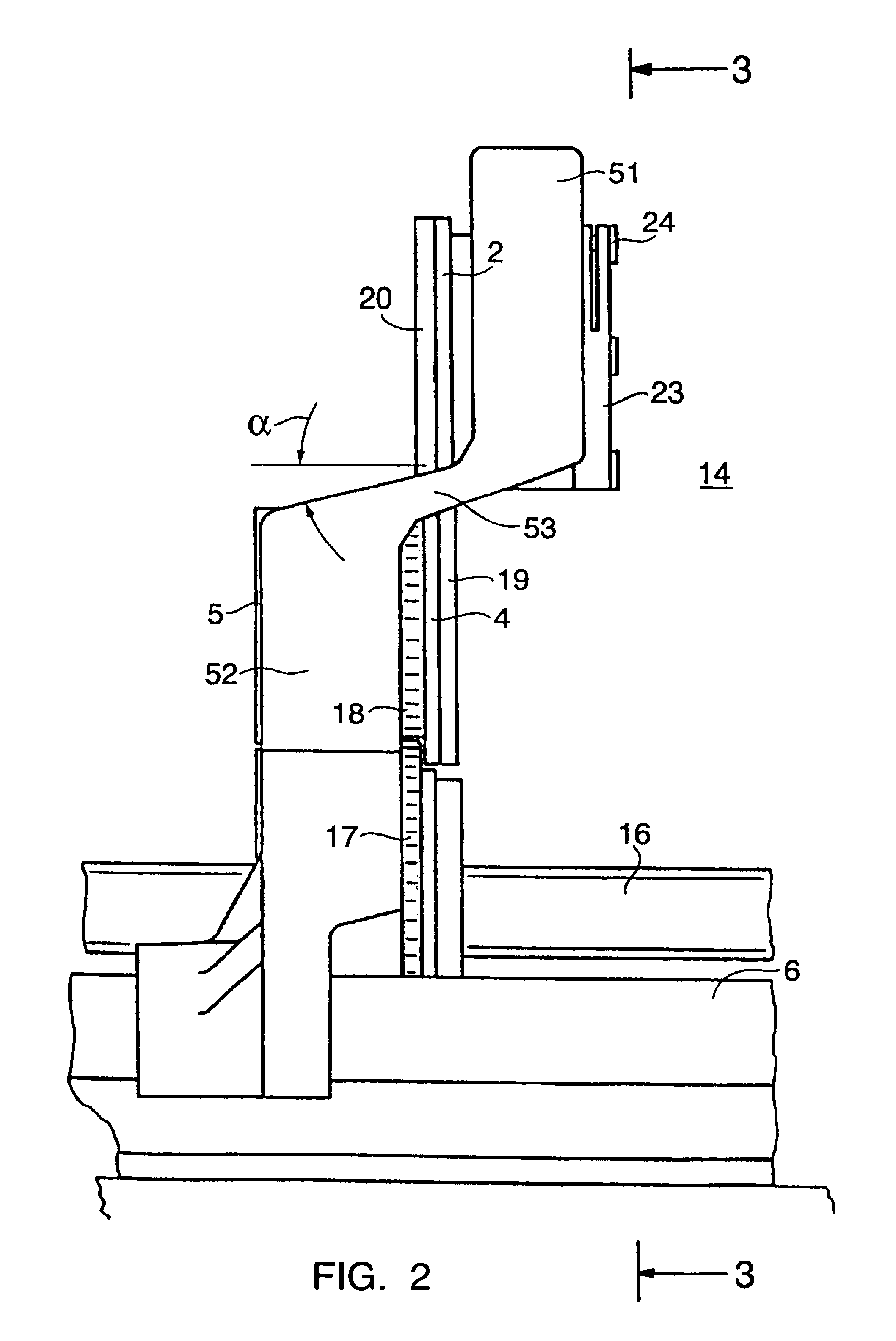
[0026]The upper circular blade 2 is affixed to an upper blade shaft 1 and the lower circular blade 4 to a lower blade shaft 3 which both extend parallel with the horizontal plane 10 and with the transverse direction 7. The two blade shafts 1, 3 are shown in detail in FIG. 4 and are supported respectively in a play-free upper blade-shaft bearing 11 and an lower blade-shaft bearing 12. Upper blade-shaft bearing 11 is mounted in a longitudinally displaceable bush 13 to allow setting of the cutting gap which is advantageously set at 0.01 to 0.02 mm for can sheet metal.

[0027]The two blade shafts 1, 3 ar...


PUM

PropertyMeasurementUnit
cutting angleaaaaaaaaaa
diameteraaaaaaaaaa
acute angleaaaaaaaaaa

Abstract

A circular-cutter unit for equipment cutting flat lengths of material and sheet metal in a horizontal plane has upper and a lower circular blades both in planes perpendicular to the horizontal plane and in a longitudinal direction, carried by an upper and lower blade shaft, respectively, which are parallel with the horizontal plane and perpendicular to the longitudinal direction. The two blade shafts are rigidly and rotatably mounted in a common frame. The frame is U-shaped with the upper and lower legs connected by a flat yoke intersecting the horizontal plane at an acute angle. Several cutter units are mounted in a single apparatus and driven by a common drive from which the units can be individually detached for servicing.

Description

CROSS-REFERENCE TO RELATED APPLICATION[0001]This application is a continuation of Ser. No. 08 / 612,212 filed Mar. 6, 1996, now abandoned, which is a continuation-in-part of application Ser. No. 08 / 182,074 filed Jan. 13, 1994 and now abandoned.FIELD OF THE INVENTION[0002]This invention relates to a circular cutting unit to cut flat lengths of materials, particularly sheet metals and especially to equipment to cut flat lengths of material using several such cutting units.BACKGROUND OF THE INVENTION[0003]Equipment of this general type is used in particular to cut sheet metal, for instance in the can manufacturing industry, although it can also be used for cutting paper and cardboard. Cutting can bodies requires extreme accuracy and cleanliness while keeping constant high outputs.[0004]French patent document 612,303 (Marinori) discloses a paper-cutting machine with two shafts mounted in a fixed frame, individual circular blades being displaceably affixed to the shafts.[0005]French patent...

Claims


Application Information

Patent Timeline
Patent Type & Authority Patents(United States)
IPC IPC(8): B26D1/24B26D7/26
CPCB26D7/2635B23D35/007Y10T83/7797Y10T83/7822Y10T83/7843Y10T83/7859Y10T83/9471
Inventor LANGHANS, RENE
Owner ELPATRONIC AG
Why Eureka
Try Eureka