Two stage mixing system for exhaust gas recirculation (EGR)

a technology of exhaust gas recirculation and mixing system, which is applied in the direction of combustion air/fuel air treatment, machines/engines, mechanical equipment, etc., can solve the problems of mixing devices that may not adequately blend the intake air with the exhaust gases, and uneven dispersion of exhaust gases in the intake air

Active Publication Date: 2006-04-18
INT ENGINE INTPROP CO LLC
View PDF8 Cites 48 Cited by
  • Summary
  • Abstract
  • Description
  • Claims
  • Application Information

AI Technical Summary

Problems solved by technology

The EGR conduit may create an obstacle that separates the intake air into two streams, each passing on an opposite side of the EGR conduit.
Many mixing devices may not adequately blend the intake air with the exhaust gases to form a combustion gas with an essentially uniform dispersion of the exhaust gases in the intake air.
While the exhaust gases and intake air are combined, there may be an uneven dispersion of the exhaust gases in the intake air.
The dispersion may be more uneven when the exhaust gases enter on one side of the intake air stream.

Method used


Image

  • Two stage mixing system for exhaust gas recirculation (EGR)
  • Two stage mixing system for exhaust gas recirculation (EGR)
  • Two stage mixing system for exhaust gas recirculation (EGR)

Examples


Embodiment Construction

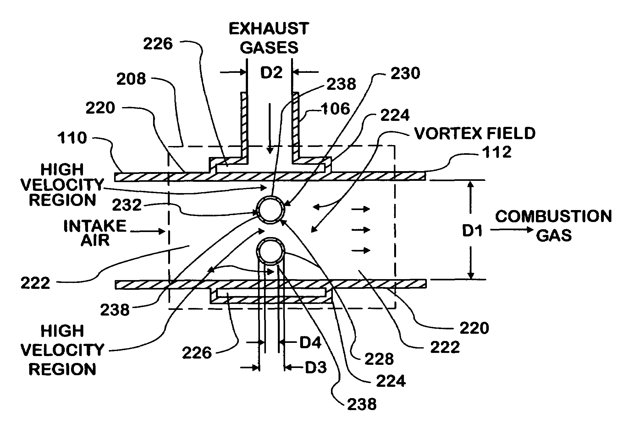
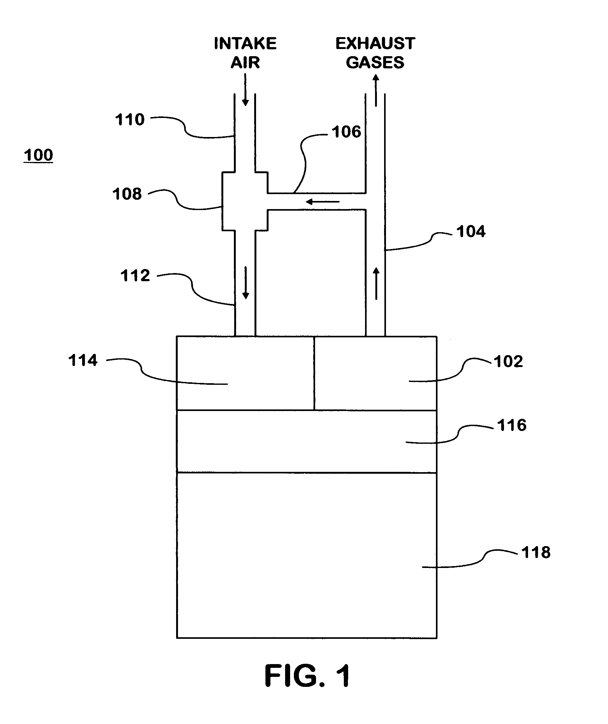
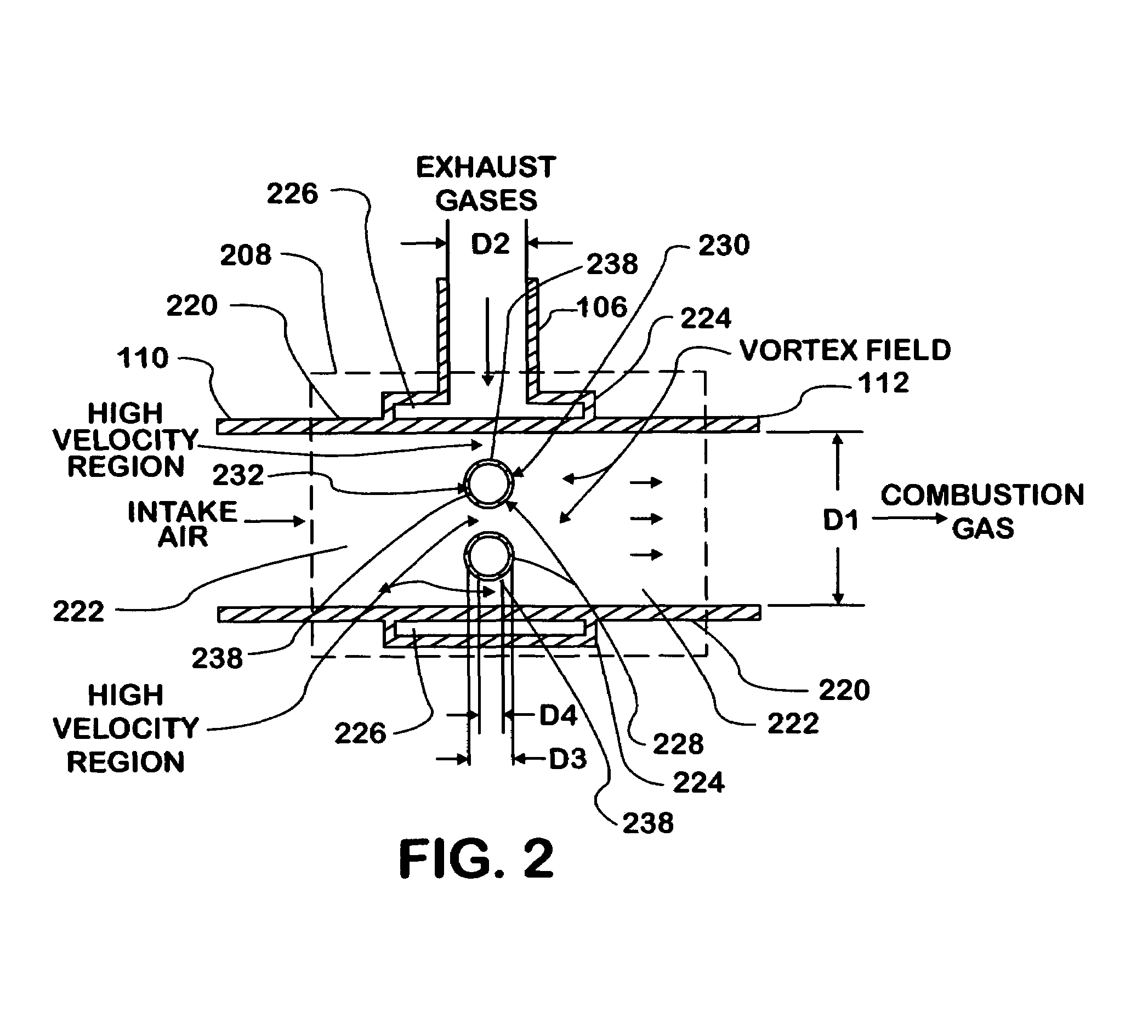
[0028]FIG. 1 is a schematic view of an internal combustion engine 100 with a two stage mixing system for exhaust gas recirculation (EGR). Exhaust gases from the internal combustion engine 100 flow through an exhaust manifold 102 into an exhaust conduit 104. The internal combustion engine 100 diverts a portion of the exhaust gases from the exhaust conduit 104 through an exhaust gas recirculation (EGR) conduit 106 into a two stage mixing device 108. Intake air for the combustion of fuel in the internal combustion engine 100 flows through an intake air conduit 110 into the two stage mixing device 108. The two stage mixing device 108 mixes the exhaust gases with the intake air in a higher velocity region (the first stage) and a vortex field (the second stage). The two stage mixing device 108 generates the higher velocity region in the intake air, directs the exhaust gases into the higher velocity region, and generates the vortex field in the combination of exhaust gases and intake air. ...


PUM


Abstract

A two stage mixing system mixes intake air with exhaust gases for exhaust gas recirculation (EGR) in an internal combustion engine. The two stage mixing system may have a two stage mixing device connected to an intake air conduit, a supply conduit, and an EGR conduit. The two stage mixing device may have a plenum disposed around a mixing conduit, which is connected to the intake air conduit and the supply conduit. The plenum is connected to one or more cross conduits and to the EGR conduit. The cross conduits extend across a mixing chamber formed by the mixing conduit. The cross conduits generate a higher velocity region in the intake air. The cross conduits direct the exhaust gases through one or more outlets into the higher velocity region. The cross conduits generate a vortex field in the exhaust gases and intake air. The exhaust gases mix with the intake air in the higher velocity region and in the vortex field.

Description

CROSS REFERENCE TO RELATED APPLICATIONS[0001]Related applications include the following commonly assigned U.S. patent applications that have been filed on the same day as this application:[0002]U.S. patent application Ser. No. 10 / 945,636, titled “Vortex Mixing System for Exhaust Gas Recirculation (EGR),” and filed on Sep. 21, 2004; and[0003]U.S. patent application Ser. No. 10 / 945,618, titled “Venturi Mixing System for Exhaust Gas Recirculation (EGR),” and filed on Sep. 21, 2004.FIELD OF THE INVENTION[0004]This invention generally relates to exhaust gas recirculation (EGR) systems in internal combustion engines. More particularly, this invention relates to EGR systems that have a mixing device to combine exhaust gases with intake air for combustion in the cylinders of an internal combustion engine.BACKGROUND OF THE INVENTION[0005]Internal combustion engines convert chemical energy from a fuel into mechanical energy. The fuel may be petroleum-based (gasoline or diesel), natural gas, a...

Claims


Application Information

Patent Timeline
Patent Type & Authority Patents(United States)
IPC IPC(8): F02M25/07
CPCF02M25/0722F02M35/10262F02M35/10222F02M25/0713F02M35/10157Y02T10/146Y02T10/121F02M26/10F02M26/19Y02T10/12
Inventor LIU, ZHENGBAIWEI, PUNING
Owner INT ENGINE INTPROP CO LLC
Why Eureka
Try Eureka