Closed loop steam cooled airfoil

a closed loop, steam-cooled technology, applied in the field of airfoil, a method of manufacturing an airfoil, and a system for cooling an airfoil, can solve the problems of affecting the thermodynamic efficiency of the power generation plant, and air having a relatively low latent specific hea

Inactive Publication Date: 2006-04-18
SIEMENS ENERGY INC
View PDF16 Cites 26 Cited by
  • Summary
  • Abstract
  • Description
  • Claims
  • Application Information

AI Technical Summary

Problems solved by technology

These high temperatures, however, can melt or otherwise harm the turbine airfoils, especially those in the first stages.
A disadvantage of this open loop cooling scheme, however, is that extracting coolant air from the compressor section causes parasitic losses to the thermodynamic efficiency of the power generation plant.
Another disadvantage of open loop cooling is that air has a relatively low latent specific heat and is therefore relatively inefficient at absorbing heat to thereby cool the airfoil.
Although a closed loop scheme is generally preferable to an open loop scheme because steam has a higher latent specific heat than air, one disadvantage of closed lo

Method used


Image

  • Closed loop steam cooled airfoil
  • Closed loop steam cooled airfoil
  • Closed loop steam cooled airfoil

Examples


Embodiment Construction

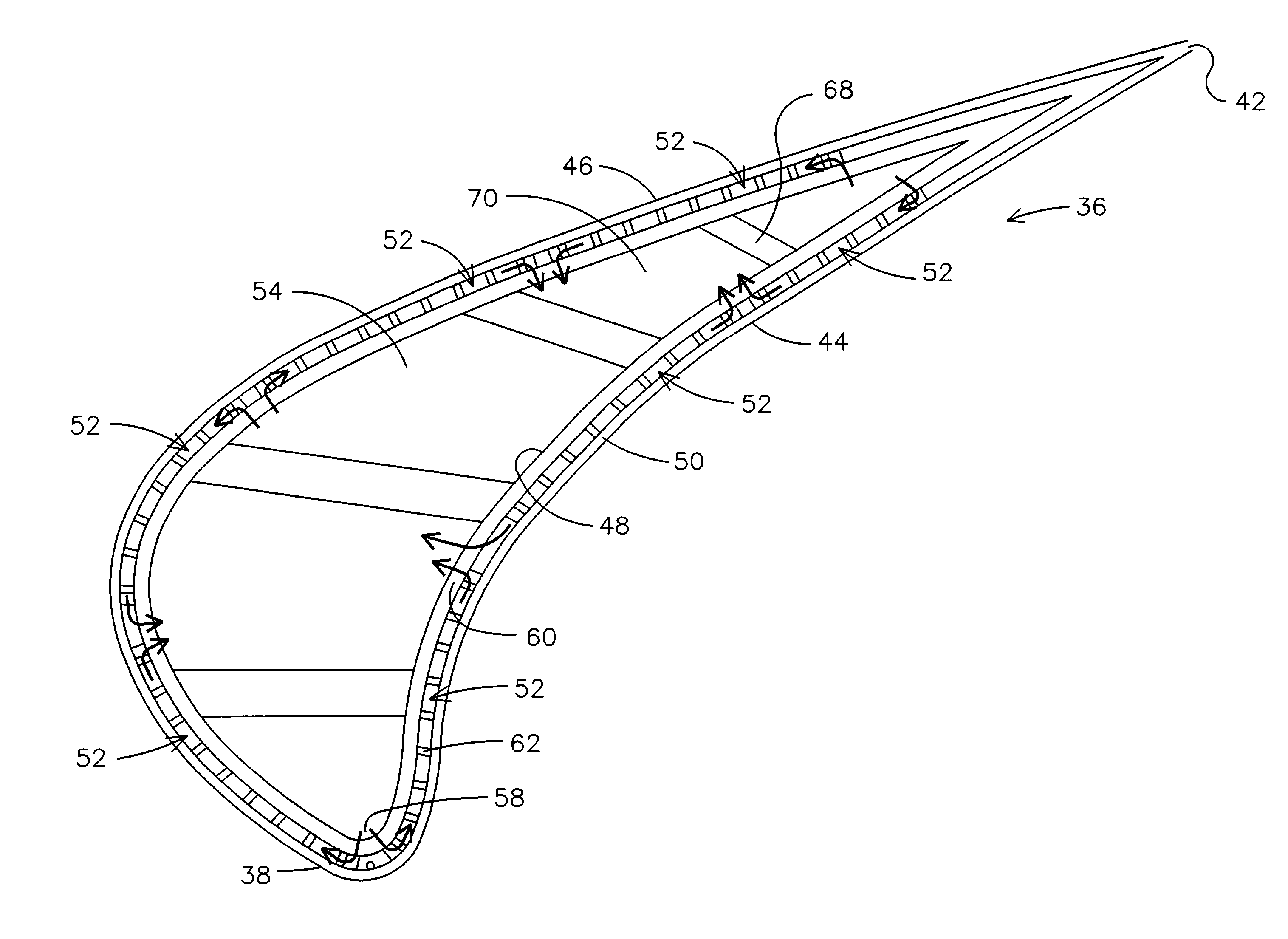
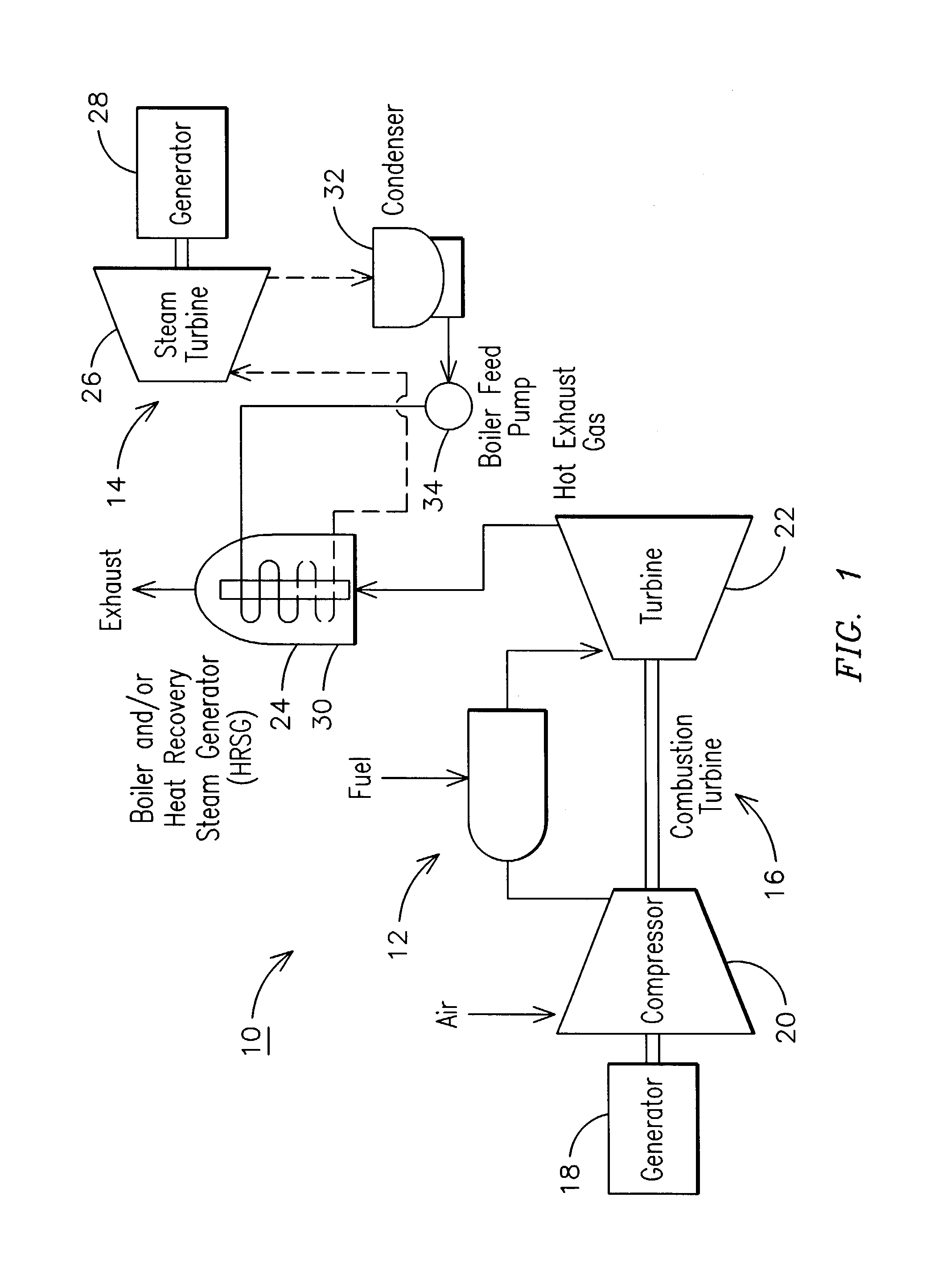
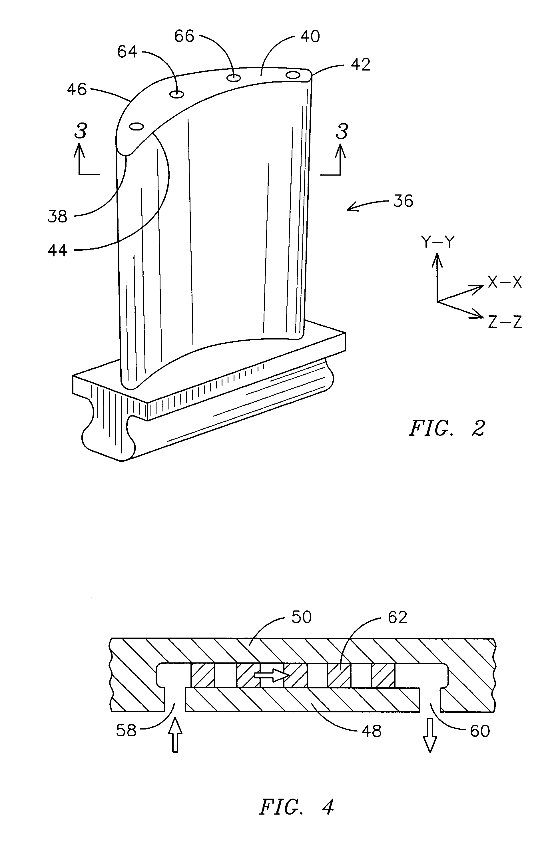
[0027]The invention described herein employs several basic concepts. For example, one concept relates to a method for cooling an airfoil located in the first stages of a combustion turbine within a combined cycle power generation plant by flowing closed loop steam through a pin array set within an airfoil. Another concept relates to a cavitied airfoil having a cooling chamber bounded by an interior wall and an exterior wall so that steam can enter the cavity, pass through the pin array, and then return to the cavity to thereby cool the airfoil. Yet another concept relates to a method of manufacturing an airfoil manufactured by a type of lost wax investment casting process in which a pin array is cast into an airfoil to form a cooling chamber. These exemplary concepts are intended to assist the reader in understanding some aspects of the present invention and are not intended to define or limit the scope of the present invention.

[0028]The present embodiment of the invention is disclo...


PUM


Abstract

An airfoil, a method of manufacturing an airfoil, and a system for cooling an airfoil is provided. The cooling system can be used with an airfoil located in the first stages of a combustion turbine within a combined cycle power generation plant and involves flowing closed loop steam through a pin array set within an airfoil. The airfoil can comprise a cavity having a cooling chamber bounded by an interior wall and an exterior wall so that steam can enter the cavity, pass through the pin array, and then return to the cavity to thereby cool the airfoil. The method of manufacturing an airfoil can include a type of lost wax investment casting process in which a pin array is cast into an airfoil to form a cooling chamber.

Description

[0001]This application is a divisional application of U.S. application Ser. No. 09 / 867,166, filed May 29, 2001, now U.S. Pat. No. 6,511,293 and claims priority thereto.GOVERNMENT RIGHTS STATEMENT[0002]This invention was conceived under United States Department of Energy Contract DE-AC05-00 OR22725. The United States Government has certain rights hereunder.FIELD OF THE INVENTION[0003]The present invention relates in general to an airfoil, a method of manufacturing an airfoil, and a system for cooling an airfoil, and, more particularly, to a thin walled pin array cast airfoil cooled through a closed loop steam cooling scheme that is located in the first stages of a combustion turbine within a combined cycle power generation plant.BACKGROUND OF THE INVENTION[0004]Many power generation plants produce electricity by converting energy (e.g. fossil fuel, nuclear fusion, hydraulic head and geothermal heat) into mechanical energy (e.g. rotation of a turbine shaft), and then converting the me...

Claims


Application Information

Patent Timeline
IPC IPC(8): B22C9/10F01D5/18
CPCF01D5/187F05D2260/2214
Inventor WIDRIG, SCOTT M.RUDOLPH, RONALD J.WAGNER, GREGG P.
Owner SIEMENS ENERGY INC
Why Eureka
Try Eureka