Power transmission system

a transmission system and power technology, applied in the direction of sealing, couplings, other domestic objects, etc., can solve the problems of easy dislocation, difficult to prevent grease filling leakage, and impaling the sealing performance, and achieve the effect of reliable sealing performance, high reliability and long-life power transmission system

Inactive Publication Date: 2006-04-18
NTN CORP
View PDF17 Cites 14 Cited by
  • Summary
  • Abstract
  • Description
  • Claims
  • Application Information

AI Technical Summary

Benefits of technology

[0015]In the present invention, the power transmission system has a gasket adhered with an adhesive sheet to at least one of an end portion of an outer joint member and the adapter attached to the end portion, or at least one of the other end portion of the outer joint member and a flange end portion of the second shaft coupled to the other end portion. When the adapter or the flange of the second shaft is attached to the outer joint member, this allows the gasket to be positioned with ease relative to the outer joint member, thereby making it possible to prevent the gasket from being dislocated and ensure reliable sealing performance. Consequently, this makes it possible to provide a highly reliable long-life power transmission system.
[0016]The power transmission system may also be configured such that an end plate for sealing the constant velocity universal joint at the other end of the outer joint member is disposed between the flange of the second shaft and the other end portion. In this case, a gasket is adhered with an adhesive sheet to at least one of an, end portion of the outer joint member and the adapter attached to the end portion, or at least one of the other end portion of the outer joint member and the end plate coupled to the other end portion. When the adapter or the end plate is incorporated into the outer joint member, this allows the gasket to be positioned with ease relative to the outer joint member, thereby making it possible to prevent the gasket from being dislocated and ensure reliable sealing performance. This provides the same effect as in the case of the adapter and the flange of the second shaft.
[0017]In the aforementioned configuration, a cylindrical portion is formed on at least one of the end plate and the adapter at an outer periphery thereof and externally fitted into an annular groove formed on an outer peripheral surface at an end portion of the outer joint member, the cylindrical portion being caulked radially inwardly at its peripheral edge to be permanently coupled to the annular groove. This allows the end plate or the adapter to be firmly incorporated into the outer joint member.
[0019]This allows the flange of the second shaft to directly contact the end portion of the outer joint member closer to its outer periphery than the end plate. This in turn makes it possible to provide highly accurate alignment between the second shaft and the outer joint member of the constant velocity universal joint, or between the second shaft and the first shaft via the constant velocity universal joint.

Problems solved by technology

Improper positioning of the gaskets 22, 23 would cause the gaskets 22, 23 to be dislocated, thereby impairing their sealing performance and making it difficult to prevent leakage of grease filled in the constant velocity universal joint 5 and intrusion of foreign material from outside.
However, there were problems with the aforementioned adapter 18 and the end plate 9 that they could be easily dislocated when incorporated into the outer ring 2.

Method used


Image

  • Power transmission system
  • Power transmission system
  • Power transmission system

Examples


Embodiment Construction

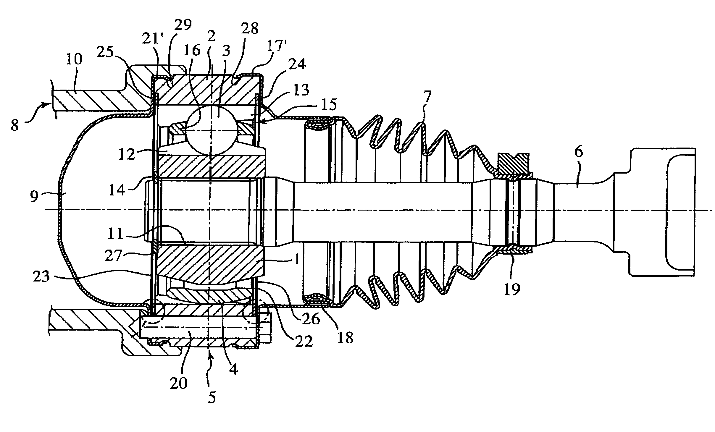
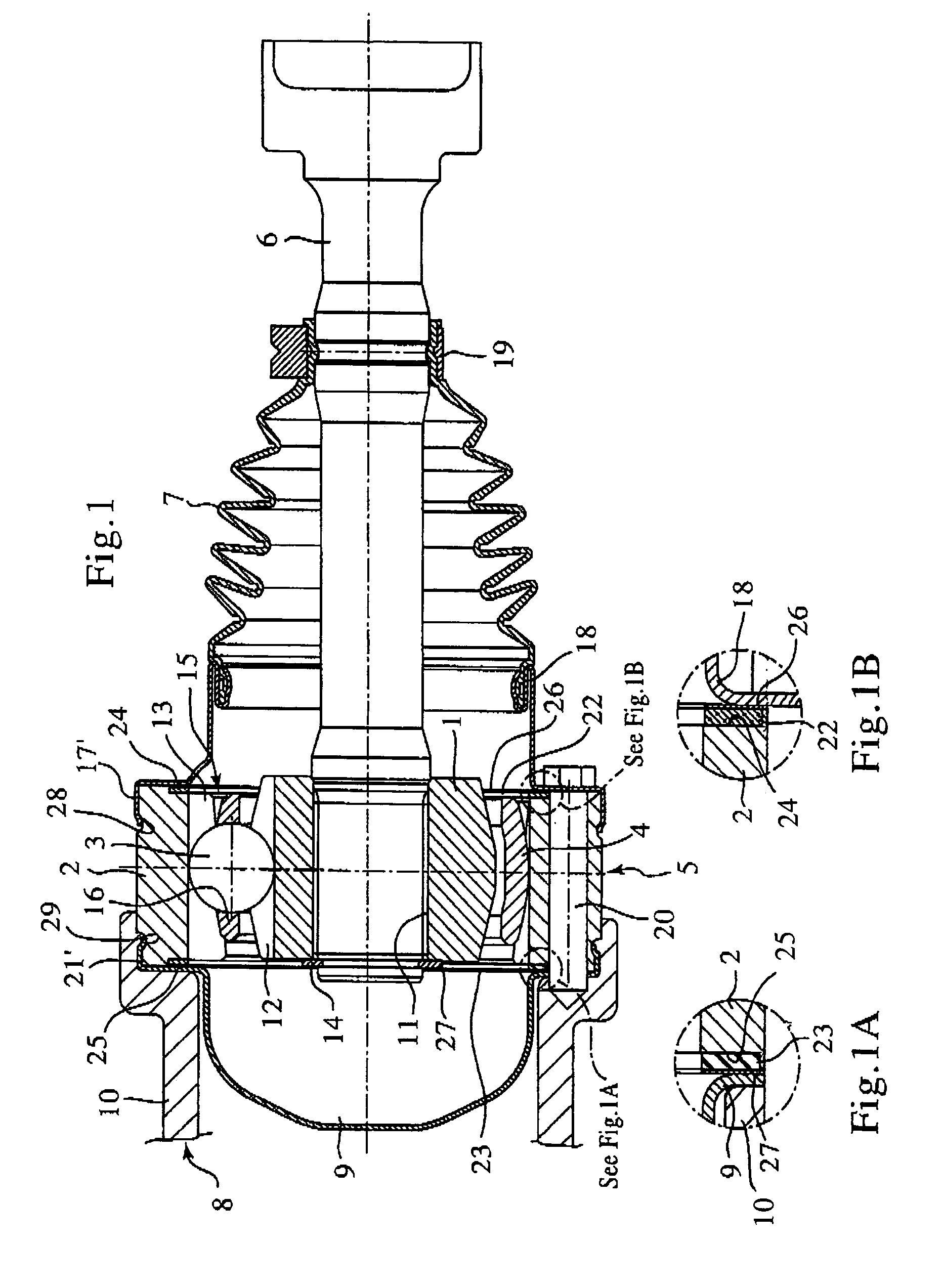
[0039]Now, a power transmission system such as a propeller shaft or a drive shaft according to an embodiment of the present invention will be explained below in detail. Reference is now made to the drawings wherein the same components as those of FIG. 7 are given the same reference numerals.

[0040]As shown in FIG. 1, the power transmission system according to this embodiment includes a Lobro (or cross groove) constant velocity universal joint 5 having an inner joint member or an inner ring 1, an outer joint member or an outer ring 2, balls 3, and a cage 4 as its primary components. The power transmission system further includes a first shaft 6 (a stub shaft) coupled to the inner ring 1 of the constant velocity universal joint 5, and a boot 7 with an adapter attached to the first shaft 6 and the constant velocity universal joint 5 to seal the constant velocity universal joint 5. The power transmission system still further includes a second shaft 8 (a stub shaft) coupled to the outer r...


PUM


Abstract

A power transmission system which facilitates positioning of gaskets to ensure their sealing performance. The power transmission system includes a constant velocity universal joint provided with an inner ring having a plurality of track grooves formed on its outer periphery and an outer ring having a plurality of track grooves formed on its inner periphery. The inner ring is disposed on the side of the inner periphery of the outer ring, wherein balls are accommodated within ball tracks formed with the track grooves of the inner and outer rings and retained by a cage. The power transmission system further includes a first shaft fitted into the inner ring to enable torque transmission, a boot with an adapter attached to the first shaft and an end portion of the outer ring to seal the constant velocity universal joint, a second shaft coupled to the outer ring with bolts, and an end plate disposed between a flange of the second shaft and the other end portion of the outer ring to seal the constant velocity universal joint. The power transmission system is configured such that gaskets are adhered with adhesive sheets to the adapter and the end plate which are attacked to the ends of the outer ring.

Description

BACKGROUND OF THE INVENTION[0001]1. Field of the Invention[0002]The present invention relates to a power transmission system that has a sealing structure, such as an end plate and a boot with an adapter, for sealing a constant velocity universal joint incorporated into an automotive propeller shaft or a drive shaft.[0003]2. Description of the Related Art[0004]As shown in FIG. 7, a power transmission system with a propeller shaft or a drive shaft for use in automobiles includes a so-called Lobro (or cross groove) constant velocity universal joint 5 having an inner ring 1, an outer ring 2, balls 3, and a cage 4 as its primary components. The power transmission system further includes a first shaft 6 (a stub shaft) coupled to the inner ring 1 of the constant velocity universal joint 5, and a boot 7 with an adapter attached to the first shaft 6 and the constant velocity universal joint 5 to seal the constant velocity universal joint 5. The power transmission system still further include...

Claims


Application Information

Patent Timeline
Patent Type & Authority Patents(United States)
IPC IPC(8): F16D3/84F16J15/10F16D3/20F16D3/227F16J3/04
CPCF16D3/227F16J3/042F16D3/845B29L2031/703Y10S277/922F16D2003/22316
Inventor OKI, TOSHIYUKINORO, YUUICHIRO
Owner NTN CORP
Why Eureka
Try Eureka