
Micro piezo-optic composite transducers and fabrication methods

a composite transducer and micro piezo-optic technology, applied in the field of transducers, can solve the problems of complex wire harnesses, difficult design, manufacture, debugging, and repair

Inactive Publication Date: 2006-04-18
GENERAL ELECTRIC CO
View PDF11 Cites 11 Cited by
  • Summary
  • Abstract
  • Description
  • Claims
  • Application Information

AI Technical Summary

Benefits of technology

"The present invention is about a new type of transducer that can convert mechanical strain into optical signals. It consists of a layer of dielectric material with electrodes on both sides, an embedded optical fiber, and embedded piezoelectric fibers. The piezoelectric fibers are positioned on either side of the optical fiber. The method for making this transducer involves positioning the electrodes and fibers on the dielectric material, and then curing it. The technical effect of this invention is that it provides a new way to measure strain and create optical signals that can be used in various applications such as sensors and optical communication systems."

Problems solved by technology

The wire harnesses have evolved over time and become extremely complex and difficult to design, manufacture, debug, and repair.
Also, although a single wire has only a small amount of copper, the weight from hundreds of wires is significant and impacts the performance of the aircraft.
These transducers are costly, heavy, and sometimes result in system failures.

Method used


Image

  • Micro piezo-optic composite transducers and fabrication methods
  • Micro piezo-optic composite transducers and fabrication methods
  • Micro piezo-optic composite transducers and fabrication methods

Examples


Embodiment Construction

[0016]Optical sensors are not limited by many of the weight and electromagnetic interference issues which impact copper based systems. Development of optical systems including optical sensors would be useful for aerospace and other complex structures for operation and health monitoring. Embodiments of the present invention relate to micro piezo-optic composite transducers (MPCTs).

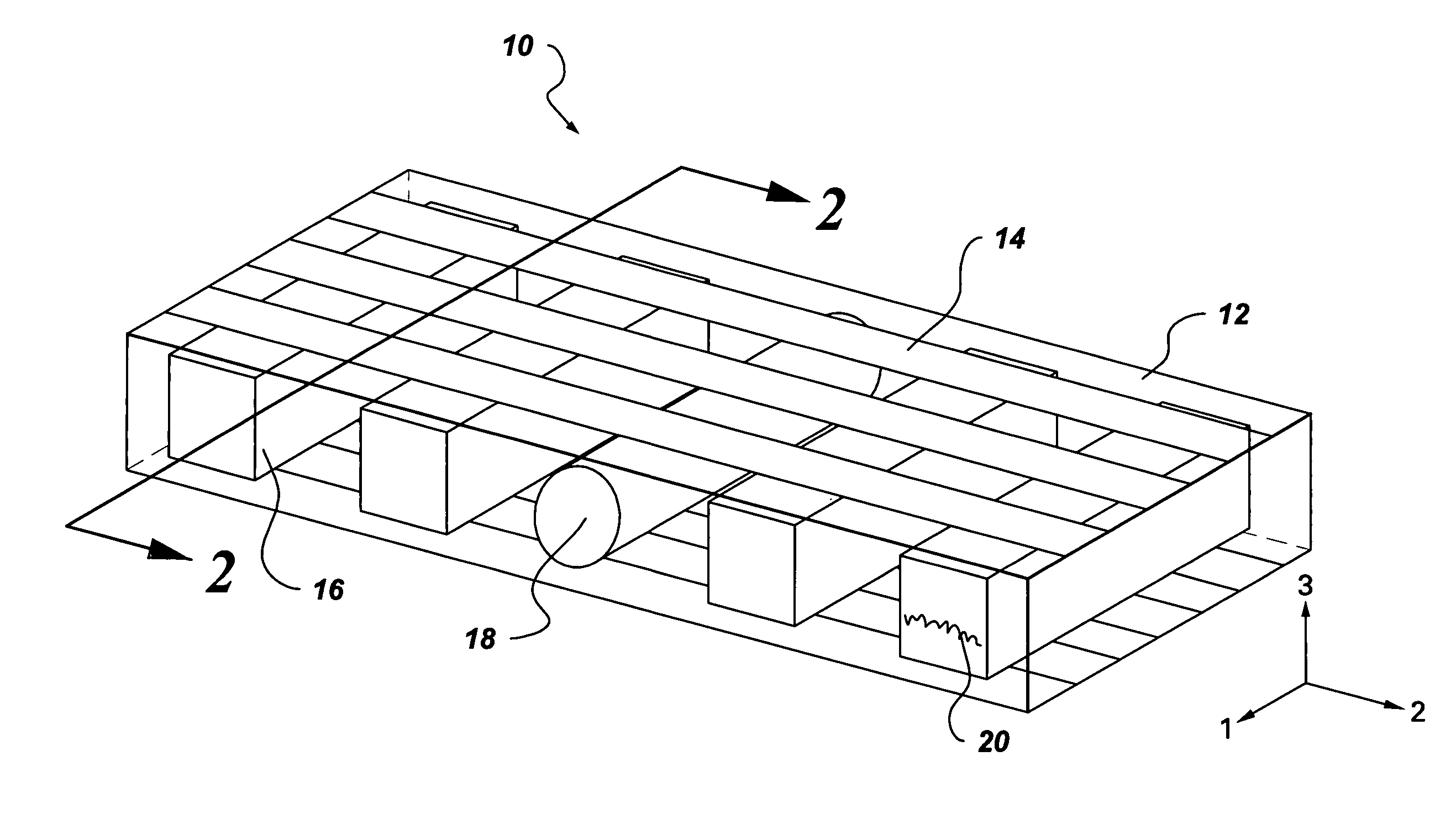
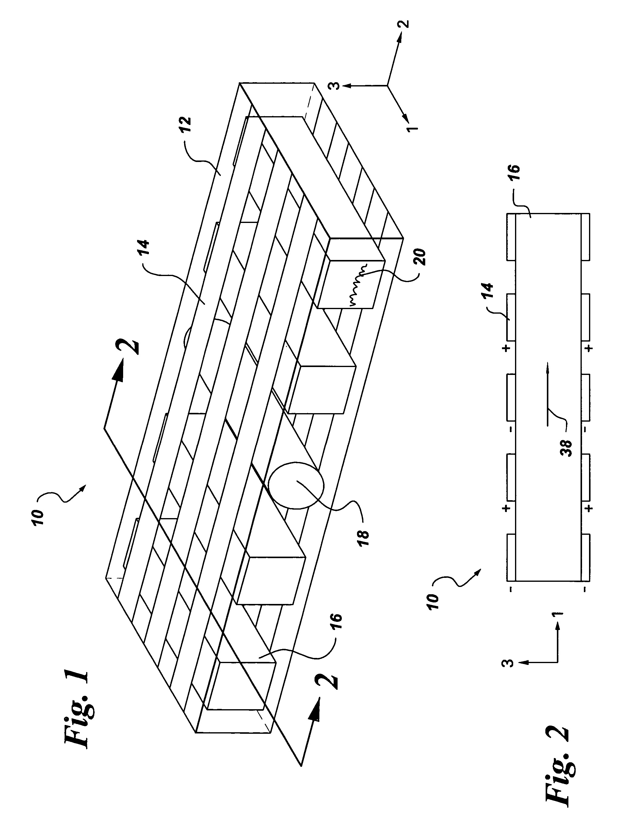
[0017]More specifically, in one embodiment of the present invention, as shown in FIGS. 1–2, MPCT 10 comprises dielectric material 12; electrodes 14 situated over opposing surfaces of the dielectric material; optical fiber 18 embedded in the dielectric material, the optical fiber configured to have a wavelength response as a function of material strain; and piezoelectric fibers 20 embedded in the dielectric material and situated on opposing sides of the optical fiber. In FIG. 2, arrow 38 represents the direction of aligned in-plane strain and electric field.

[0018]Using embodiments of the present invention, a...


PUM

PropertyMeasurementUnit
temperaturesaaaaaaaaaa
wavelength responseaaaaaaaaaa
piezoelectricaaaaaaaaaa

Abstract

A micro piezo-optic composite transducer comprises: dielectric material; electrodes situated over opposing surfaces of the dielectric material; an optical fiber embedded in the dielectric material, the optical fiber configured to have a wavelength response as a function of material strain; and piezoelectric fibers embedded in the dielectric material and situated on opposing sides of the optical fiber.

Description

BACKGROUND[0001]The invention relates generally to transducers.[0002]Structures used in aerospace applications such as aircraft components typically have integrated sensors and actuators. The actuators are used to drive electric valves, pumps, jacks, and other devices used in normal aircraft operation. Additional electronic devices may be used for avionics, surveillance, jamming, communication, or other functions. Each of these electronic devices typically has at least one current or voltage sensor. Such sensors can monitor the power consumption and indicate if there is a problem or failure of a particular device. Many motor drives for actuation on avionic or other applications include closed loop control embodiments that depend upon sensing current, voltage, or a combination of current and voltage.[0003]In conventional aircraft systems, the output of the current and voltage sensors is linked to a flight control computer or other control electronics equipment through a wire harness ...

Claims


Application Information

Patent Timeline
Patent Type & Authority Patents(United States)
IPC IPC(8): G01J1/04G01J4/00G01B11/16G01J5/08G01M5/00G01M11/08G01R15/24G02B6/02
CPCG01B11/18G01M5/0041G01M11/086G01R15/24G01M5/0091G02B6/022
Inventor SEELEY, CHARLES ERKLINNIELSEN, MATTHEW CHRISTIANKOSTE, GLEN PETER
Owner GENERAL ELECTRIC CO
Learn More