Electro-luminescence display device and driving method thereof

a technology of electro-luminescence display device and driving method, which is applied in the direction of static indicating device, solid-state device, instruments, etc., can solve the problems of undesired non-uniformity of brightness with which pictures are displayed by the first and second el panels within the electro-luminescence display device, and difficulty in maintaining substantially identical threshold voltage vth across a plurality of el panels

Active Publication Date: 2006-04-18
LG DISPLAY CO LTD
View PDF6 Cites 25 Cited by
  • Summary
  • Abstract
  • Description
  • Claims
  • Application Information

AI Technical Summary

Benefits of technology

[0025]An advantage of the present invention provides an electro-luminescence display device and a method of driving the same capable of compensating differences in brightness to which pictures are displayed by panels in an electro-luminescence display device.
[0026]Additional features and advantages of the invention will be set forth in the description which follows, and in part will be apparent from the description, or may be learned by practice of the invention. These and other advantages of the invention will be realized and attained by the structure particularly pointed out in the written description and claims hereof as well as the appended drawings.
[0027]To achieve these and other advantages and in accordance with the purpose of the present invention, as embodied and broadly described, an electro-luminescence display device may, for example, include: a panel having data lines; a supply voltage source for applying a supply voltage; a data driver for driving the data lines in response to externally inputted digital data signals; a gamma voltage generator for generating gamma voltages, the gamma voltages being usable in forming analog data signals corresponding to the externally inputted digital data signals; and a threshold voltage compensator arranged between the gamma voltage generator and the supply voltage source for controlling the supply voltage and for applying the controlled supply voltage to the gamma voltage generator.
[0028]In one aspect of the present invention, the panel may, for example, include pixels arranged in a matrix pattern, wherein each pixel includes an electro-luminescence cell and a drive thin film transistor for applying a current to the electro-luminescence cell, wherein the applied current corresponds to a reference voltage, wherein the reference voltage is substantially equal to the difference between a threshold voltage of the drive thin film transistor and the supply voltage.
[0029]In another aspect of the present invention, the threshold voltage compensator may lower a voltage level of the supply voltage and apply the lowered supply voltage to the gamma voltage generator.
[0030]In yet another aspect of the present invention, the threshold voltage compensator may apply a reference voltage to the gamma voltage generator, wherein the reference voltage is substantially equal to the difference between a threshold voltage of the drive thin film transistor and the supply voltage; and the gamma voltage generator may divide the reference voltage.

Problems solved by technology

However, use of newly developed flat panel displays such as liquid crystal displays (LCDs), field emission displays (FEDs), plasma display panels (PDPs), and electro-luminescence (EL) devices are becoming increasingly common due to their low weight, thin dimensions, and low power consumption.
Maintaining substantially identical threshold voltages Vth across a plurality of EL panels can be difficult because threshold voltages Vth of drive TFTs T2 typically vary with the manner in which the TFTs were fabricated.
If threshold voltages of drive TFT T2 in different EL panels 20 are different, the brightness at which pictures are displayed by EL panels within the electro-luminescence display device becomes undesirably non-uniform.
Accordingly, the brightness with which pictures are displayed by the first and second EL panels within the electro-luminescence display device is undesirably non-uniform due to differences in threshold voltages Vth of the related art drive TFTs T2 within the first and second EL panels.

Method used


Image

  • Electro-luminescence display device and driving method thereof
  • Electro-luminescence display device and driving method thereof
  • Electro-luminescence display device and driving method thereof

Examples


Embodiment Construction

[0068]Reference will now be made in detail to embodiments of the present invention, examples of which are illustrated in the accompanying drawings.

[0069]FIG. 5 illustrates an electro-luminescence display device according to the principles of a first aspect of the present invention.

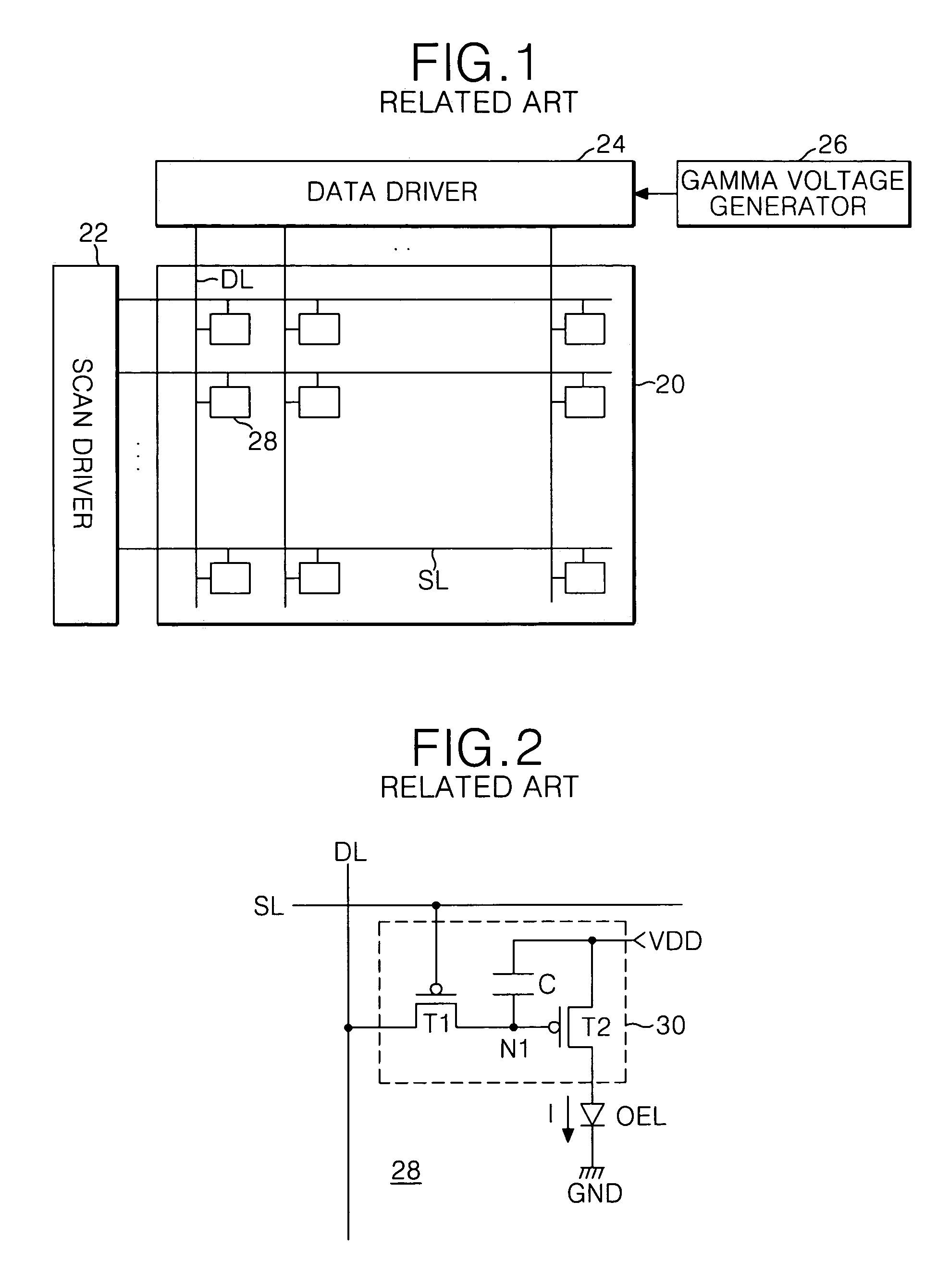
[0070]Referring to FIG. 5, an electro-luminescence (EL) display device according to the principles of the present invention may, for example, include an EL panel 40 having a plurality of pixels 48 arranged at areas defined by crossings of scan lines SL and data lines DL, a scan driver 42 for driving the scan lines SL of the EL panel 40, a data driver 44 for driving the data lines DL of the EL panel 40, and a gamma voltage generator 46 for applying a plurality of gamma voltages to the data driver 44.

[0071]The scan driver 42 may sequentially apply scan pulses to the scan lines SL, to sequentially drive the scan lines SL, and the data driver 44 may convert externally inputted digital data signals into analog ...


PUM


Abstract

An electro-luminescence display device includes a supply voltage source; a data driver for driving a plurality of data lines arranged within a panel; a gamma voltage generator for generating gamma voltages to generate analog data voltages corresponding to externally inputted data signals provided to the data driver; and a threshold voltage compensator installed between the gamma voltage generator and the supply voltage source for controlling a supply voltage of the supply voltage source and to apply the controlled voltage to the gamma voltage generator.

Description

[0001]This application claims the benefit of Korean Patent Application Nos. P2002-84784 filed Dec. 27, 2002 and P2002-88204 filed on Dec. 31, 2002, which are hereby incorporated by reference for all purposes as if fully set forth herein.BACKGROUND OF THE INVENTION[0002]1. Field of the Invention[0003]The present invention relates to electro-luminescence display devices and methods of driving the same, and more particularly to an electro-luminescence display device and a method of driving the same, capable of compensating differences in brightness to which pictures are displayed by panels in an electro-luminescence display device.[0004]2. Description of the Related Art[0005]Until recently, cathode ray tubes (CRTs) have generally been used in display systems. However, use of newly developed flat panel displays such as liquid crystal displays (LCDs), field emission displays (FEDs), plasma display panels (PDPs), and electro-luminescence (EL) devices are becoming increasingly common due t...

Claims


Application Information

Patent Timeline
Patent Type & Authority Patents(United States)
IPC IPC(8): G09G3/30H01L51/50G09G3/20G09G3/32
CPCG09G3/2011G09G3/3225G09G3/3233G09G2300/026G09G2300/0819G09G2330/02G09G2310/027G09G2320/0233G09G2320/0276G09G2320/043G09G2300/0842
Inventor HA, YONG MINCHUNG, HOON JULEE, HAN SANGLEE, MYUNG HOJEONG, SEOK HEE
Owner LG DISPLAY CO LTD
Why Eureka
Try Eureka