Time domain equalizer for DMT modulation

a time domain equalizer and dmt technology, applied in the field of data communication, can solve the problems of reducing the efficiency of transmission, and reducing the orthogonality of subchannels, so as to maximize channel capacity and optimize the effect of shortening the effective transmission channel respons

Inactive Publication Date: 2006-04-18
TEXAS INSTR INX
View PDF5 Cites 15 Cited by
  • Summary
  • Abstract
  • Description
  • Claims
  • Application Information

AI Technical Summary

Benefits of technology

[0022]It is therefore an object of the present invention to provide a time domain equalizer that optimally shortens the effective transmission channel response to maximize channel capacity.
[0027]The present invention may be implemented into a receiver, such as used in a DSL transceiver operating according to discrete multitone modulation. In this invention, a time domain equalizer is provided for effectively reducing the length of the transmission channel response to below a limit corresponding to the length of a cyclic prefix included with each block of transmitted time-domain data. The time domain equalizer is designed according to a constrained mean-squared-error minimization of the channel response and time domain equalizer, where the constraint is a frequency domain flatness constraint of arbitrary phase.

Problems solved by technology

ICI affects the independence of the subcarriers, resulting in loss of orthogonality among the subchannels.
Of course, if the subchannels are no longer orthogonal to one another, the modulating data on these subchannels cannot be separated at the receiver.
Because the cyclic prefix does not itself contain any information or “payload” (considering that the prefix is redundant with the samples at the end of the block), a cyclic prefix of any length reduces the efficiency of the transmission.
In many DSL subscriber loops, the transmission channel response may indeed be very long, requiring an extremely long cyclic prefix, and resulting in a significant loss of data rate.
Conventional optimization of a time domain equalizer in an ADSL modem therefore involves difficult tradeoffs.
In theory, a time domain equalizer can be derived that compensates both for a long channel response and also a sharp high-pass filter characteristic, however such a conventional time domain equalizer will necessarily be quite complex.
In addition, the resulting TEQ will add significant energy into the low-frequency band due to the high-pass filtering, which will necessarily amplify noise in this band and cause it to spread into the low-frequency symbols, reducing the signal-to-noise ratio and also impacting resolution of the TEQ coefficients for high frequency components.
By way of further background, it has been observed that the frequency domain behavior of conventional MMSE TEQs when applied to FDM modems is quite poor.
Near nulls often result in the passband region, while the downstream DFT demodulation process causes appreciable spectral leakage of noise power between adjacent frequency bins, including into the near null frequencies.
These near nulls therefore result in a loss of channel capacity.

Method used


Image

  • Time domain equalizer for DMT modulation
  • Time domain equalizer for DMT modulation
  • Time domain equalizer for DMT modulation

Examples


Embodiment Construction

[0033]The present invention will be described in connection with an example of its implementation in a transceiver, such as a Digital Subscriber Line (DSL) modem. It will be apparent to those skilled in the art having reference to this specification that this invention is particularly well-suited for use in such an application. However, it is also contemplated that this invention will be of similar benefit in many other applications that involve the use of a time domain equalizer, particularly in its application of shortening the impulse response of a transmission channel. It is therefore to be understood that these and other alternatives to the embodiment described below are contemplated to be within the scope of the invention as claimed.

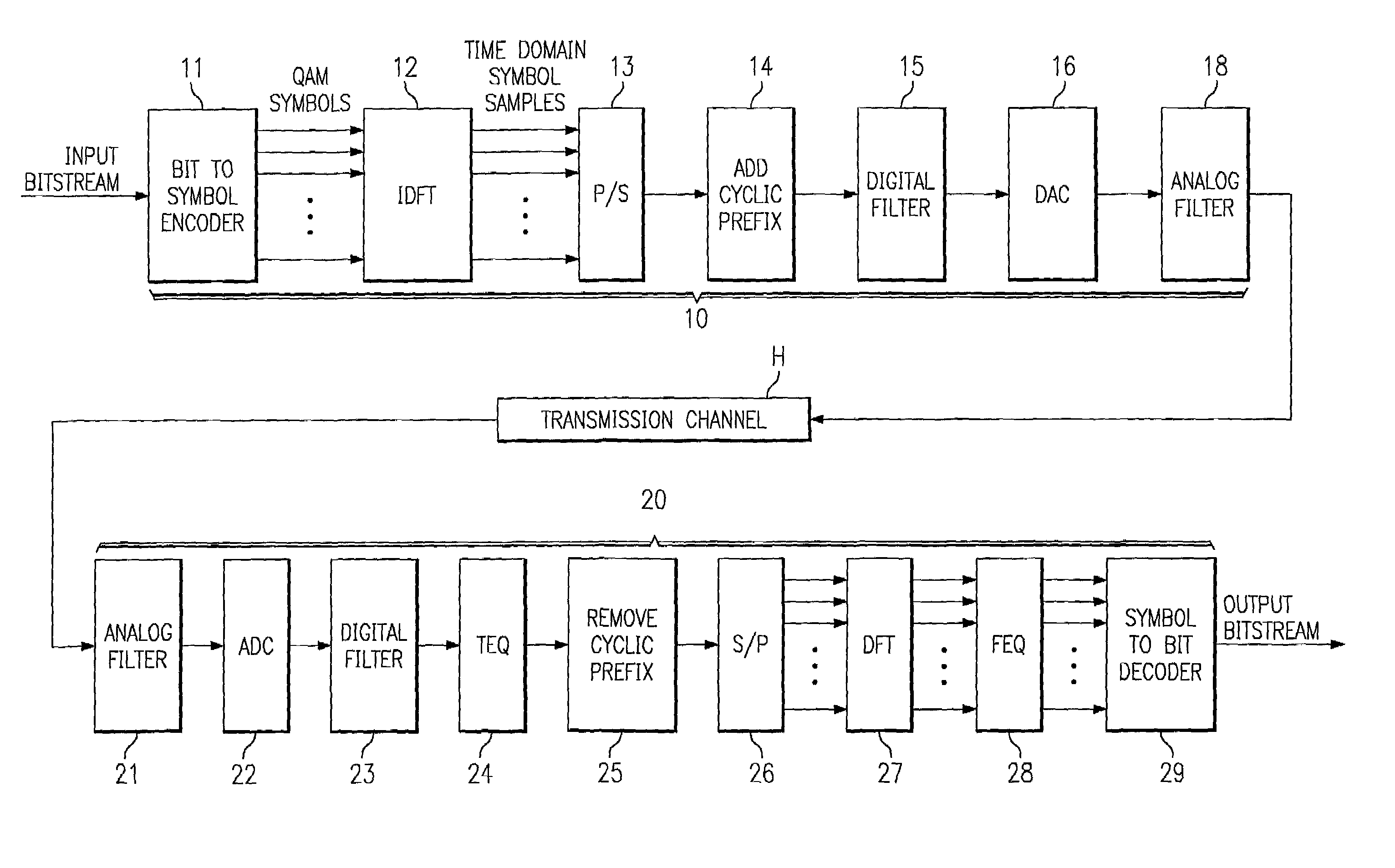
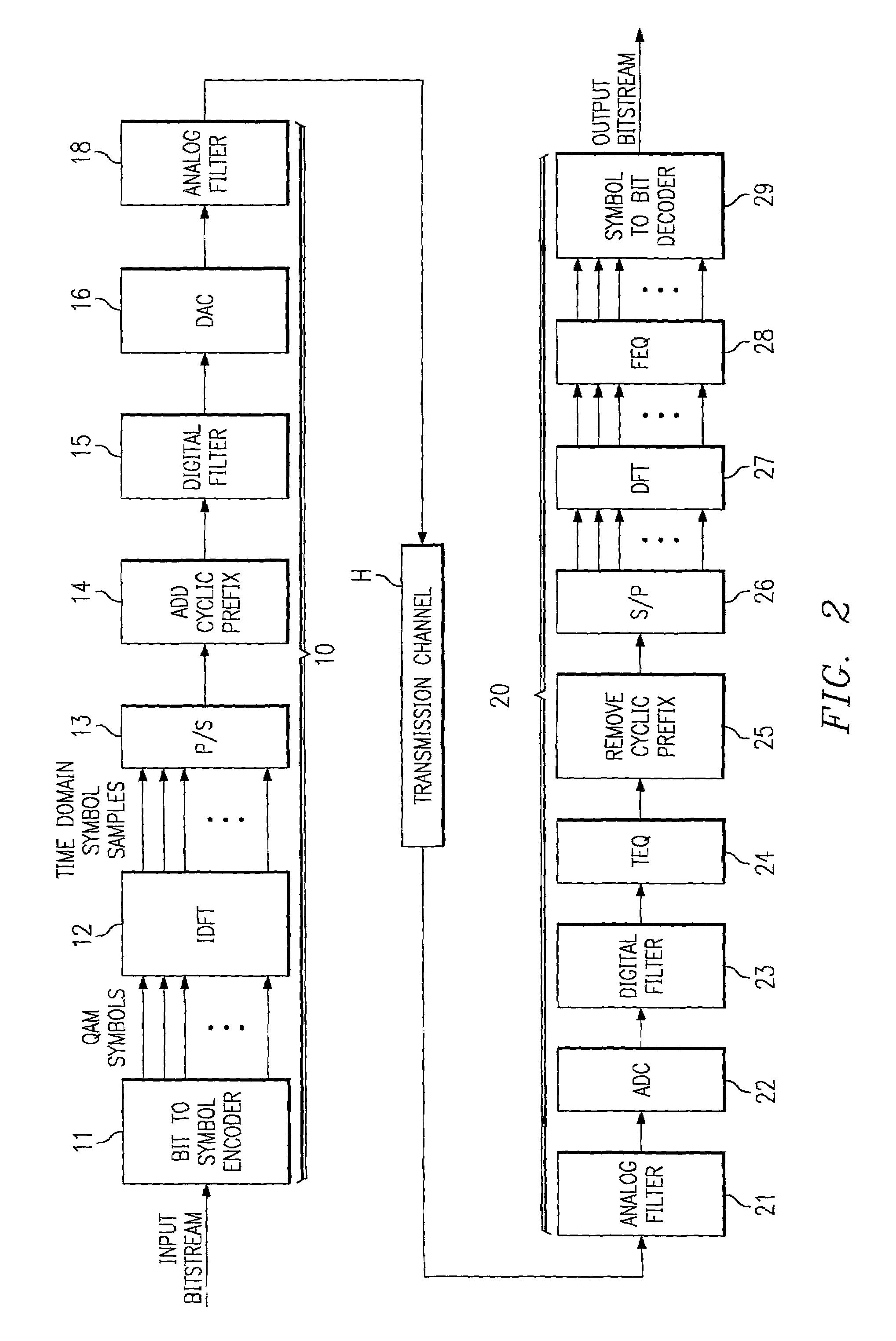
[0034]FIG. 2 functionally illustrates an example of a DSL communication system into which the preferred embodiment of the invention is implemented. In the system of FIG. 2, only one direction of transmission (from transmitting modem 10 to receiving...


PUM


Abstract

A method for deriving coefficients for a time domain equalizer function (24) as implemented by a digital signal processor (35) in a DSL modem (20) is disclosed. A transmitting modem (10), such as at a central office, issues a pseudo-random training sequence that is received by the receiving modem (20). Correlation matrices are derived by the digital signal processor (35), from which sets of eigenvalues and eigenvectors are derived. A flatness constraint on the frequency response of the time domain equalizer is established, and included with a flatness scaling factor (λ) into a minimization cost function. One or more values of the flatness scaling factor (λ), preferably between minimum and maximum eigenvalues, are evaluated in the cost function, to derive the optimum filter for the time-domain equalizer. The flatness constraint ensures that the time-domain equalizer is not subject to near null conditions and large variations in its frequency response.

Description

CROSS-REFERENCE TO RELATED APPLICATIONS[0001]Not applicable.STATEMENT REGARDING FEDERALLY SPONSORED RESEARCH OR DEVELOPMENT[0002]Not applicable.BACKGROUND OF THE INVENTION[0003]This invention is in the field of data communications, and is more specifically directed to modulator / demodulators (modems) for use in such communications.[0004]As is well-known in the art, many modern data communications utilize multicarrier modulation (MCM) to provide high data rates. According to this technology, multiple carrier-modulated data streams are transformed into a single waveform for transmission; the inverse transformation at the receiver separate the multiple carriers, and recover the modulating symbols. MCM techniques are used in such communications applications as such as Digital Subscriber Line (DSL) services, fixed wireless, digital audio broadcast (DAB), and terrestrial digital video broadcast (DVB-T). MCM fundamentals are described in Bingham, “Multicarrier Modulation for Data Transmissi...

Claims


Application Information

Patent Timeline
Patent Type & Authority Patents(United States)
IPC IPC(8): H04B1/38H04L5/16H04L25/03
CPCH04L25/03038H04L2025/03414
Inventor SESTOK, IV, CHARLES K.WARKE, NIRMAL C.
Owner TEXAS INSTR INX
Why Eureka
Try Eureka