

Magnetic circuit for speaker with short-circuiting ring
a short-circuiting ring and magnetic circuit technology, applied in the direction of deaf-aid sets, electrical transducers, transducer details, etc., can solve the problems of increasing the cost of magnets, not promising much effect, reducing the magnetic flux density, etc., and achieves the effect of reducing the current distortion, simple and easy attachment, and effective suppression of total harmonic distortion
Inactive Publication Date: 2006-04-18
MINEBEA CO LTD
View PDF22 Cites 10 Cited by
- Summary
- Abstract
- Description
- Claims
- Application Information
AI Technical Summary
Benefits of technology
The solution significantly reduces current distortion and total harmonic distortion, enhances sound pressure in the high-frequency region, and maintains magnetic flux density, while being cost-effective and easy to attach.
Problems solved by technology
In the above conventional measures, in which the short-circuiting ring as the secondary winding of the voice coil is shorted thereby reducing the inductance of the voice coil, and is disposed outside the center pole or inside the magnet thereby holding down a second harmonic distortion, the gap may possibly be expanded thereby reducing the magnetic flux density, and also the short-circuiting ring attached near the magnet has little influence on an impedance in a high-frequency region thus not promising much effect.
This, however, invites an increase in magnet cost, raising problems with practical use.
Method used
View moreImage
Smart ImageViewing Examples

Examples
working example
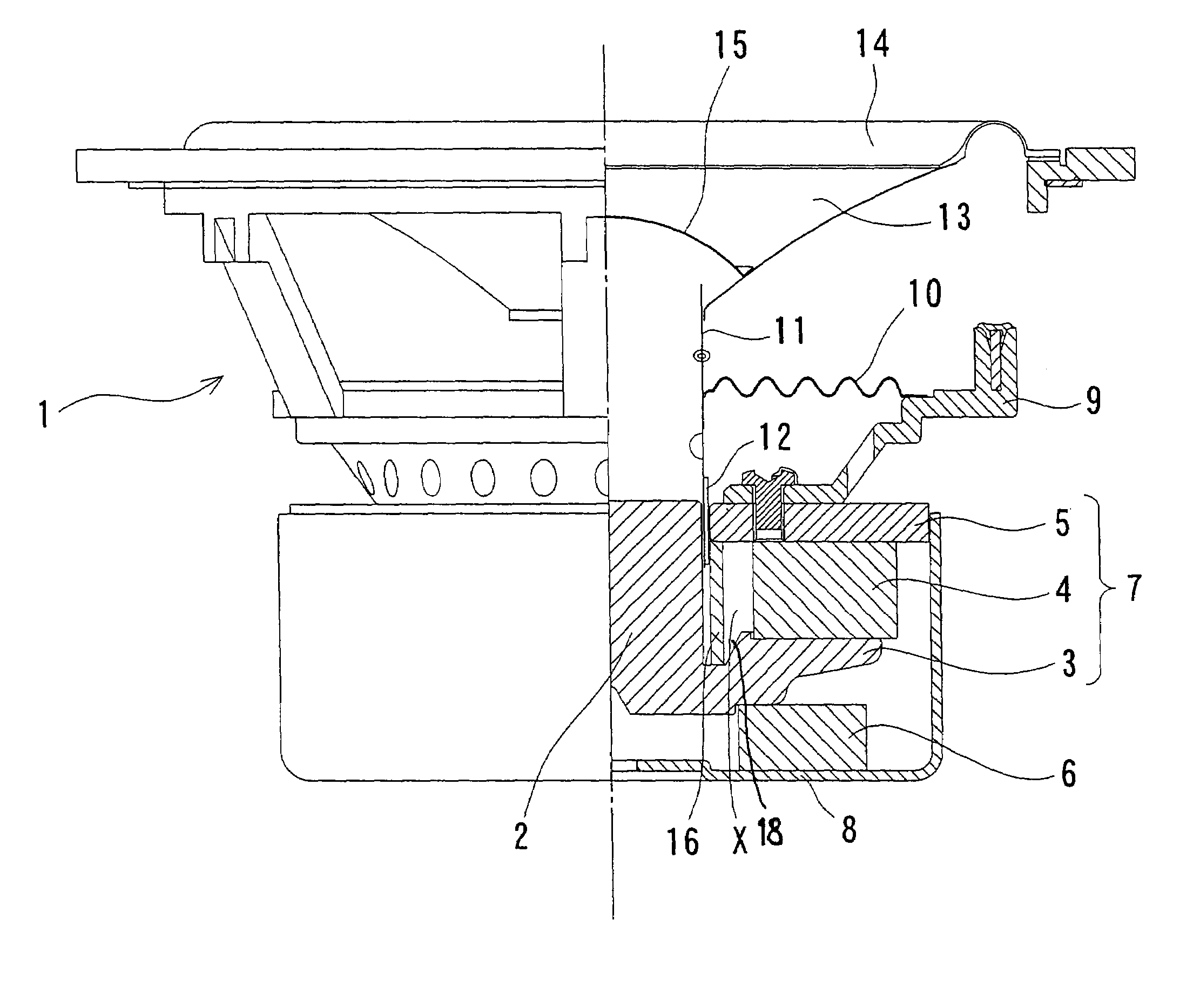
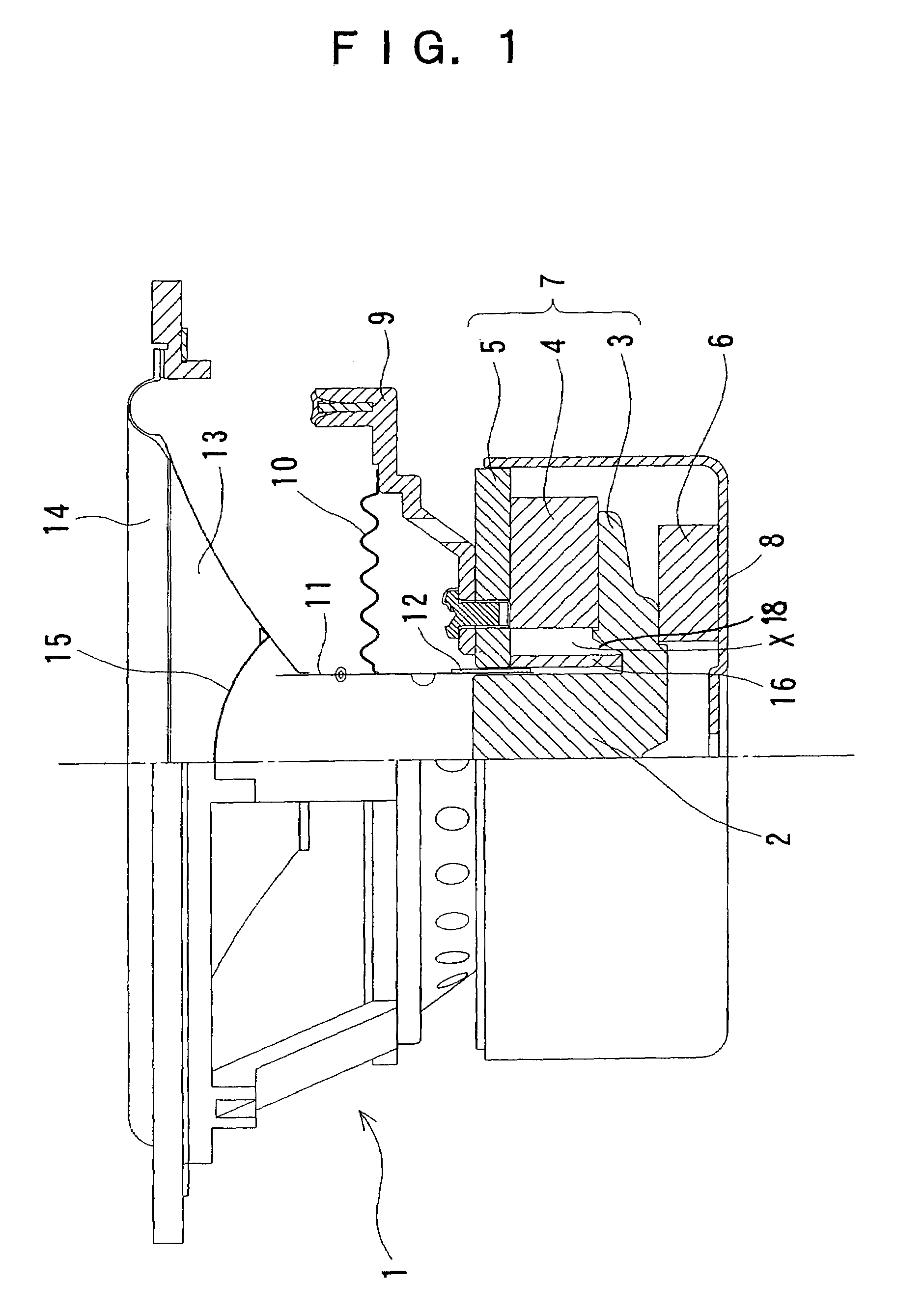
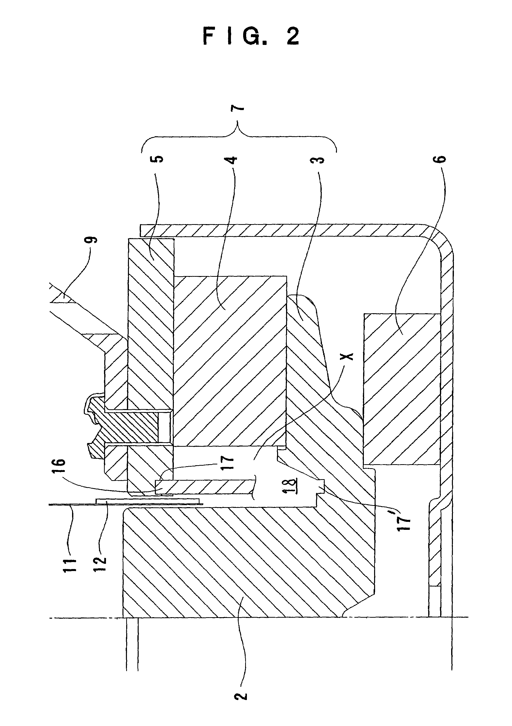
[0027]A dynamic cone speaker with a magnetic circuit shown in FIG. 1 was produced. The dynamic cone of the speaker has a diameter of 150 mm, and the short-circuiting ring is made of aluminum and has a length of 19 mm and a thickness of 2 mm, and the voice coil has an impedance of 4 Ω. The admittance curve (impedance curve) and sound pressure frequency characteristics of this speaker are shown in FIG. 3, and the characteristics of the total harmonic distortion (THD), second harmonic distortion and third harmonic distortion are shown in FIG. 5.
Login to View More PUM
 Abstract
A magnetic circuit for a speaker comprises: a bottom yoke including a center pole; a ring magnet; a top plate; and a short-circuiting ring shaped like a hollow cylinder. The short-circuiting ring is disposed close and parallel to a voice coil and attached to the inner portion of the bottom of the top plate.
Description
BACKGROUND OF THE INVENTION[0001]1. Field of the Invention[0002]The present invention relates to a magnetic circuit for a speaker, especially a cone speaker for use in various audio equipments.[0003]2. Description of the Related Art[0004]It is well known that in a cone speaker, a current strain, which is attributable to a change in the position of a voice coil relative to a gap incurred by a large amplitude of bass, or attributable to a magnetic material forming a magnetic circuit, is conventionally addressed, for example, such that a short-circuiting ring made of copper or aluminum is put inside a pole piece or magnet and shorted thereby reducing an inductance of the voice coil closer to zero.[0005]A short-circuiting ring disclosed in Japanese Patent No. 2737273 is made of a copper plate, formed into a cylinder, and attached to a center pole so as to be concentric with and parallel to a voice coil. The short-circuiting ring is adapted to short an eddy current flowing in the center ...
Claims
Login to View More Application Information
Patent Timeline
 Patent Type & AuthorityPatents(United States)
IPC IPC(8): H04R25/00H04R9/02
CPCH04R9/025H04R2209/022H04R2400/00
InventorAMINO, KENTA
OwnerMINEBEA CO LTD