Active rollover protection

a technology of active rollover and protection, applied in the direction of electric control, instruments, cycle equipment, etc., can solve the problems of reducing the accuracy of evaluating rollover tendencies and the high cost of roll rate sensors, and achieve the effect of reducing the roll moment of the vehicl

Active Publication Date: 2006-04-18
CONTINENTAL AUTOMOTIVE SYST INC
View PDF59 Cites 15 Cited by
  • Summary
  • Abstract
  • Description
  • Claims
  • Application Information

AI Technical Summary

Benefits of technology

[0004]One embodiment of the present invention provides a method for protecting against rollover in a vehicle, the method including the steps of providing an array of linear acceleration sensors and providing a control module to utilize the array of sensors. The array of acceleration sensors are positioned at predetermined locations relative to the center of gravity of the vehicle. The control module includes, among other things, a model of the vehicle dynamics and a model of the array of sensors. An acceleration is detected for each sensor in the array. The roll angle of the vehicle is then estimated based on the detected accelerations, the model of the vehicle dynamics and the model of the sensors. The method then generates a control signal based on the roll angle, and reduces the roll moment of the vehicle based on the control signal.
[0005]According to more detailed aspects, the method may further comprise the step of estimating a roll rate based on the detected accelerations, the model of the vehicle dynamics and the model of the sensors. Likewise, the method may further estimate the roll acceleration based on the same accelerations and models. Thus, the control signal may be based on both the roll angle and the roll rate, or alternatively the roll angle, the roll rate and the roll acceleration, thereby increasing the precision of the control signal. The step of estimating a roll angle preferably includes estimating a state vector representing the dynamic conditions of the vehicle. The state vector includes a roll angle, a roll rate, a yaw rate and a lateral velocity of the vehicle.
[0007]Another embodiment of the present invention provides a method for protecting against rollover in a motor vehicle, the vehicle defining a longitudinal axis, a lateral axis, and a vertical axis. The method includes the steps of providing an acceleration sensor positioned along the lateral axis of the vehicle. The sensor is spaced a distance from the center of gravity. An acceleration on the vehicle is detected with the sensor, and a roll acceleration of the vehicle is determined from the detected acceleration and the known position of the sensor. The roll acceleration is integrated to determine a roll rate and a roll angle of the vehicle. A control signal is generated based on the roll angle, the roll rate and the roll acceleration, and the roll moment of the vehicle is reduced based on the control signal.
[0009]Another embodiment of the present invention provides a system for protecting against rollover in a vehicle. The system includes an array of linear acceleration sensors, a control module and an actuator. The control module includes a signal adjuster, an estimator, a signal generator, a model of the vehicle dynamics and a model of the array of sensors. The sensors are positioned at predetermined locations relative to the center of gravity of the vehicle, each sensor detecting a linear acceleration along its sensor axis. The signal adjuster receives the detected accelerations and transforms them from a sensor coordinate system to a body coordinate system. The estimator receives the transformed accelerations and estimates a roll angle based on the transformed accelerations, the model of the vehicle dynamics, and the model of the array of sensors. The signal generator generates a control signal when the estimated roll angle indicates a tendency of the vehicle to roll over. The actuator receives the control signal and reduces the roll moment of the vehicle based thereon.

Problems solved by technology

Unfortunately, such roll rate sensors are expensive due to their complicated nature.
Further, reliance only on the roll rate may result in reduced precision when evaluating rollover tendencies.

Method used


Image

  • Active rollover protection
  • Active rollover protection
  • Active rollover protection

Examples


Embodiment Construction

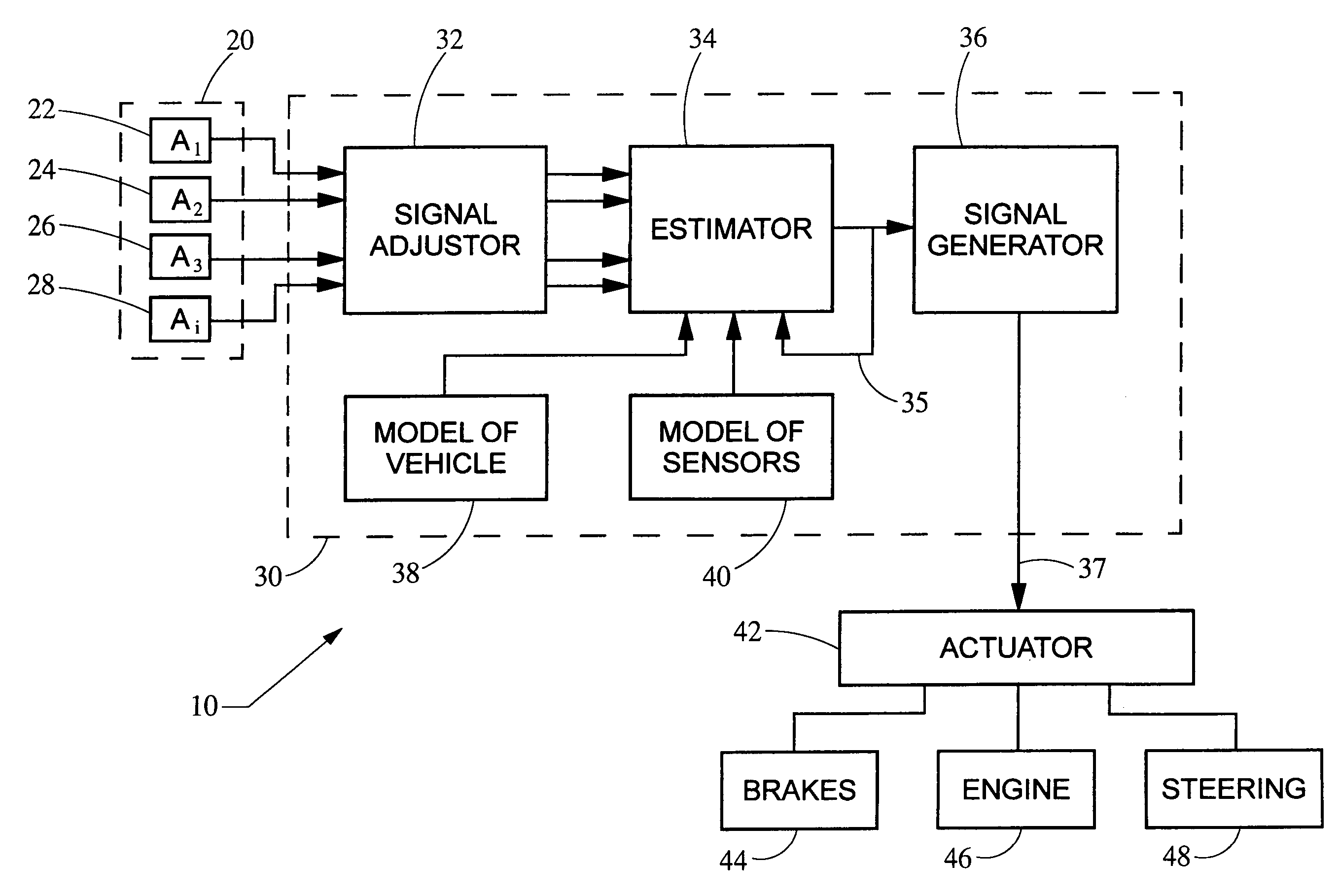
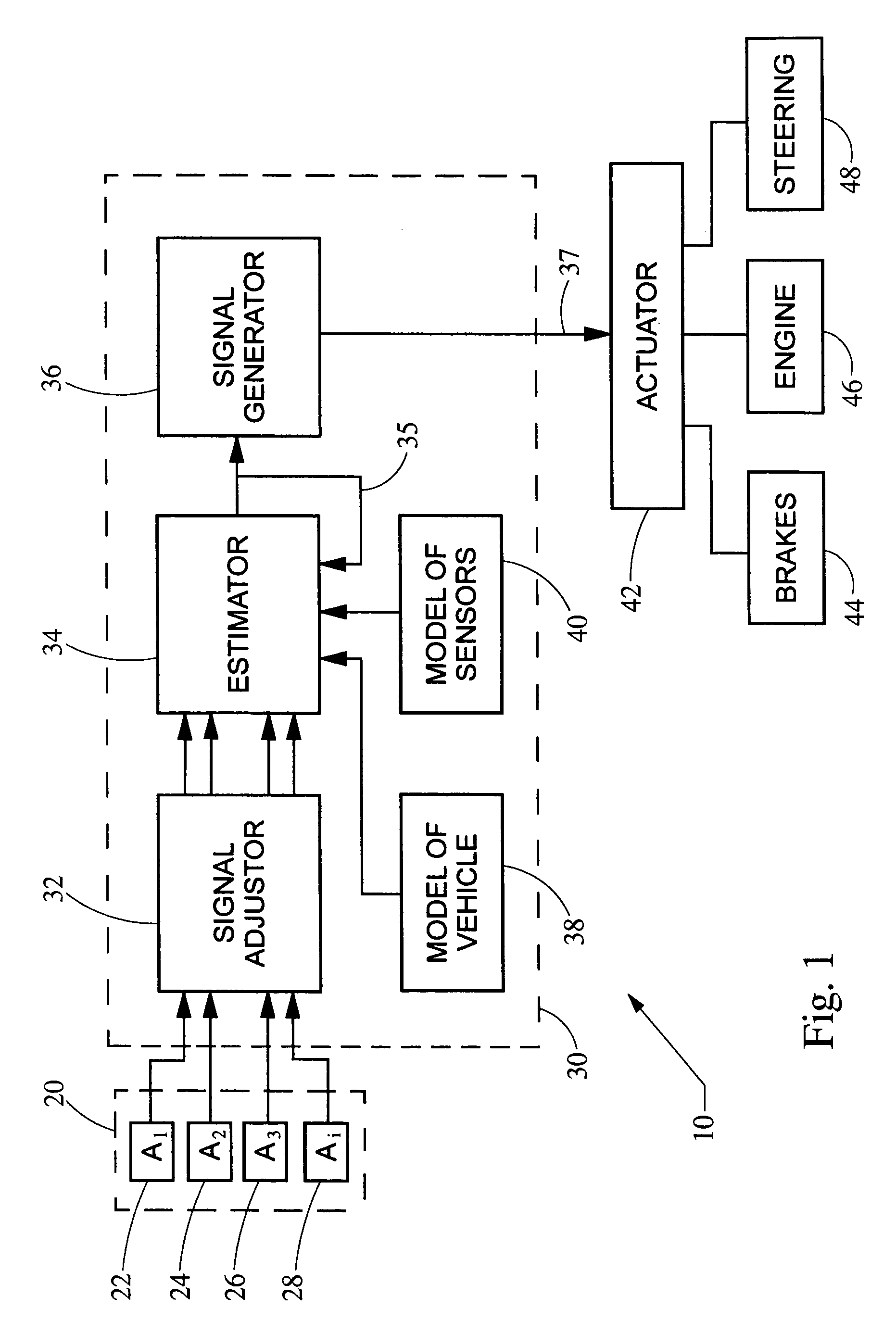
[0015]Turning now to the figures, FIG. 1 depicts an active rollover protection system 10 constructed in accordance with the teachings of the present invention. The system 10 generally includes an array of acceleration sensors 20, a control module 30, and an actuator 42. The array of sensors 20 detect a set of linear accelerations, which is used by the control module 30 to evaluate the dynamic condition of the vehicle, and in particular the tendency of the vehicle to rollover. If the control module 30 determines there is a tendency of the vehicle to rollover, it sends a signal to the actuator 42, which in turn reduces the rollover moment of the vehicle 70 (FIG. 3) through application of the vehicle brakes or throttling of the engine or by actively controlling the steering of the vehicle.

[0016]The array of sensors 20 generally include any number of acceleration sensors such as a A1 22, A2 24, A3 26 up to Ai 28. A simple example of the array of sensors 20 is depicted in FIG. 3. As show...


PUM


Abstract

A system and method protects against rollover in a vehicle by employing an array of linear acceleration sensors. A control module includes, among other things, a model of the vehicle dynamics and a model of the array of sensors. A state vector is estimated based on the detected accelerations, the model of the vehicle dynamics and the model of the sensors. A control signal is generated based on the state vector, and the roll moment of the vehicle is reduced based on the control signal.

Description

FIELD OF THE INVENTION[0001]The present invention relates generally to stability control systems for motor vehicles, and more particularly relates to active rollover protection for such stability control systems.BACKGROUND OF THE INVENTION[0002]In recent years, much attention has been paid to the reduction of rollover in motor vehicles, especially in larger vehicles such as sport-utility vehicles (SUV's) which have a relatively high center of gravity. These vehicles may experience friction induced rollover conditions, in which the vehicle can rollover in response to friction forces acting on the vehicle tires without striking an obstacle.[0003]Vehicle rollover is caused by exceeding the critical roll angle for a particular vehicle. The roll angle is the function of the suspension of the vehicle, the vehicle's loading condition and other vehicle characteristics and dynamic conditions. Existing rollover protection systems employ some form of a predictive means in an attempt to predict...

Claims


Application Information

Patent Timeline
Patent Type & Authority Patents(United States)
IPC IPC(8): G06F17/00B60W30/04B60R16/02B60R21/01B60T8/172B60T8/1755B60T8/58B60W10/00B60W10/04B60W10/06B60W10/18B60W10/20B60W40/10F02D29/02F02D45/00G01P15/00
CPCB60W30/04B60W40/10B60T2230/03B60W10/06B60W10/18B60W2520/18B60W10/20
Inventor LEHMANN, KURF STOUFFERHILDEBRAND, BRIAN L.SCHUMANN, CLINTONBAUER, GEOFFREY BURKE
Owner CONTINENTAL AUTOMOTIVE SYST INC
Why Eureka
Try Eureka