
Lock, particularly a tailgate lock for a motor vehicle

a tailgate lock and motor vehicle technology, applied in the field of locks, can solve the problems of large construction and relatively large construction of conventional locks which perform the specified functions, and achieve the effect of constant step-up ratio and minimising spa

Inactive Publication Date: 2006-04-25
INTIER AUTOMATIVE CLOSURES INC
View PDF9 Cites 34 Cited by
  • Summary
  • Abstract
  • Description
  • Claims
  • Application Information

AI Technical Summary

Benefits of technology

[0006]The problem of the present invention is therefore to improve vehicle locks so that they are smaller and lighter in construction compared with conventional designs and are also cheaper to produce. The invention also sets out to make vehicle locks as quiet as possible.
[0007]By means of the measure according to the invention of having an electric motor drive operatively connected to a lock mechanism by means of various clutches, particularly of identical construction, depending on the direction of driving, different functions of the lock mechanism can be achieved in a minimal space simply and inexpensively. In particular, by providing different directions of rotation of the drive in the lock according to the invention, mechanical stops which stop the kinematic processes of the lock mechanism at precisely defined positions can easily be converted in construction.
[0009]According to a preferred embodiment of the lock according to the invention, at least one of the minimum of two clutches is constructed as a centrifugal clutch. By the use of centrifugal clutches, manual operation of the system can be ensured even in the event of a loss of current or failure of the drive. As the clutch is an essential component for realising a “reset” function, there is thus no need to integrate an additional component in the lock to cover the eventuality of loss of power. Another major advantage of a centrifugal clutch is that it only engages and performs the desired function upwards of a certain speed, i.e. at a predetermined power level. As a centrifugal clutch cannot provide any frictional engagement without a power supply, mechanical operation of the lock in the event of a power failure is substantially simpler. The use of centrifugal clutches allows the system to be returned to the original position. At the same time the clutch separates the gear wheel system or lock mechanism from the drive.
[0013]The lock mechanism appropriately has a multiple step-up, particularly using gear wheels. By the use of gear wheels and / or levers to produce this multiple step-up, the necessary forces for producing a sealing force between a boot lid and the vehicle body can be provided while at the same time minimising the space taken up. The use of gear wheels in particular makes it possible for the force-transmitting components to engage constantly with one another so that, in contrast to conventional constructions with levers as the force transmitters, uniform transmission, i.e. a constant step-up ratio, can be achieved.

Problems solved by technology

Conventional locks which perform the functions specified have proved to be relatively large and heavy in construction.

Method used


Image

  • Lock, particularly a tailgate lock for a motor vehicle
  • Lock, particularly a tailgate lock for a motor vehicle
  • Lock, particularly a tailgate lock for a motor vehicle

Examples


Embodiment Construction

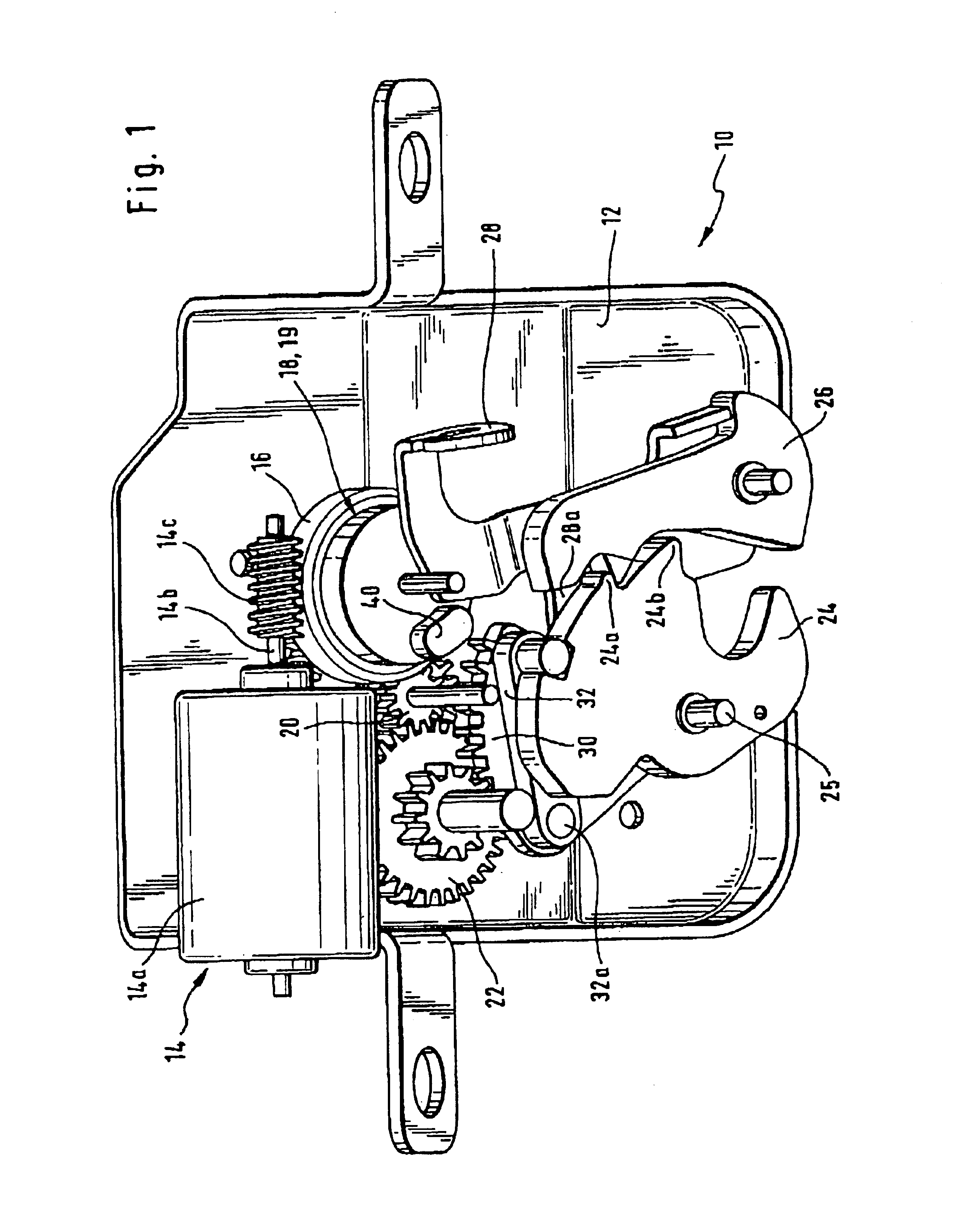
[0024]A preferred embodiment of the lock according to the invention is shown in perspective view in FIG. 1 and generally designated 10. The components of the drive and the lock mechanism are mounted on a baseplate 12.

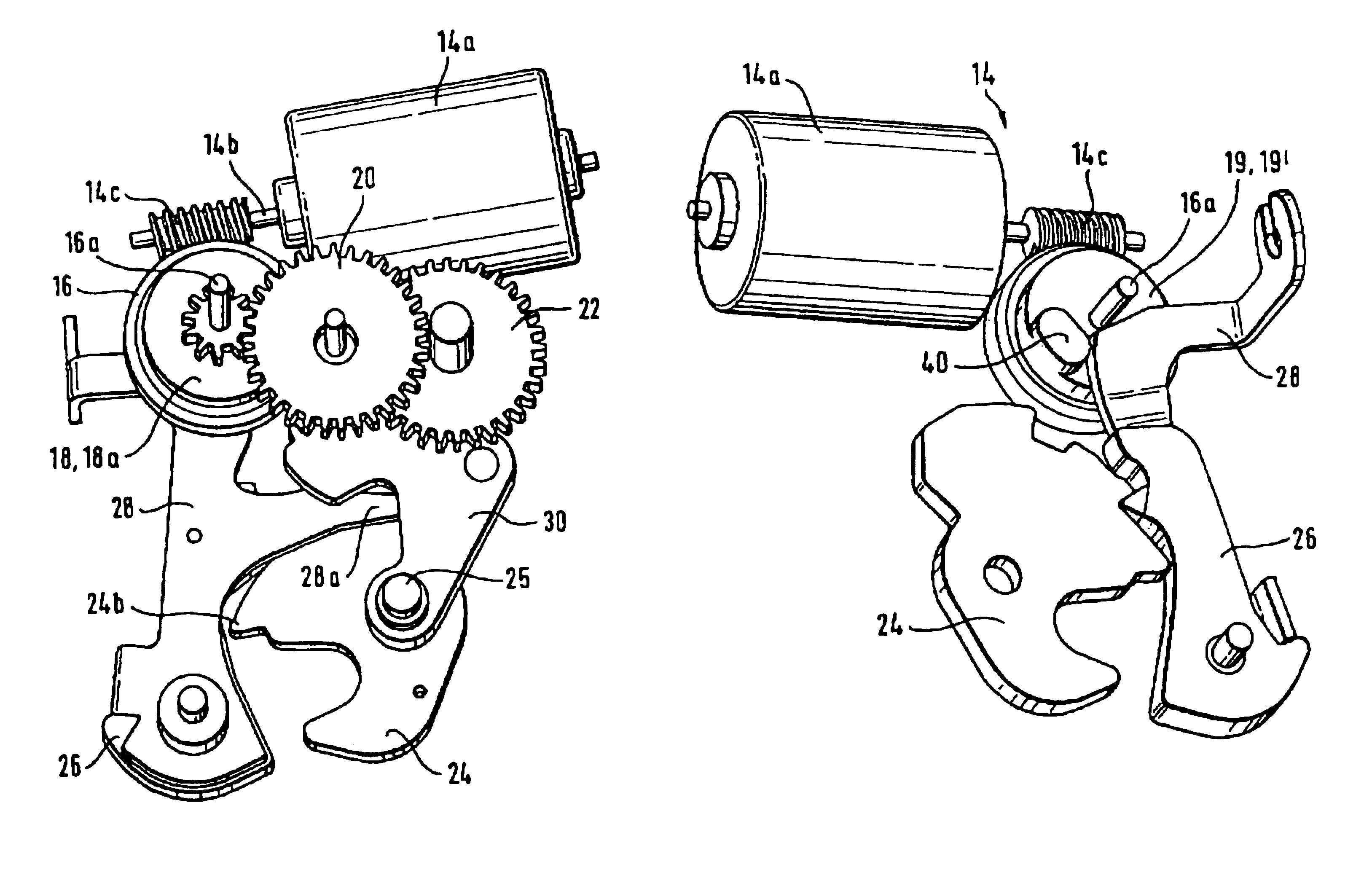
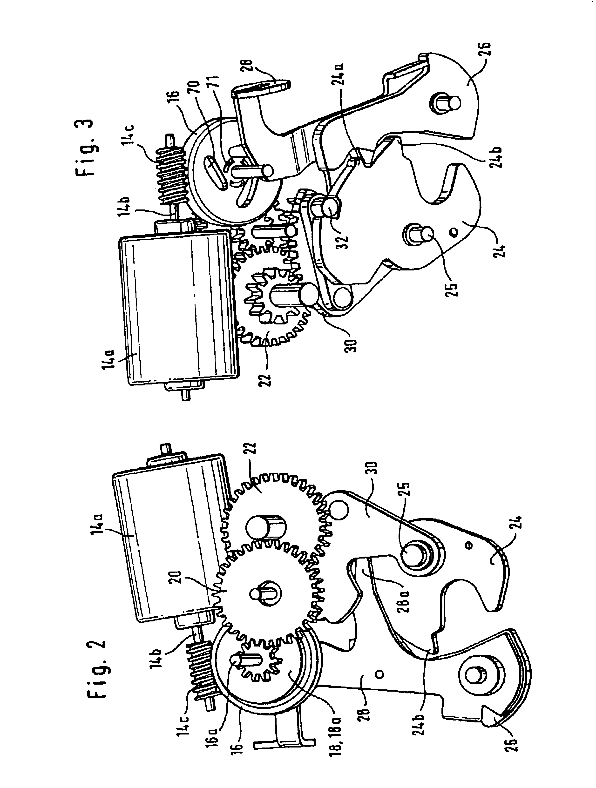
[0025]A drive 14 has a reversing electric motor 14a with a motor shaft 14b attached thereto which is constructed with a gear 14c in the form of a worm gear, for example. The drive 14 is operatively connected to a main gear wheel 16 rotatable about a rotation spindle 16a by means of the worm gear 14c. The main gear wheel 16 is shown without teeth to simplify the drawing. A double centrifugal clutch 18, 19 is provided on the main gear wheel 16. This centrifugal clutch comprises a first centrifugal clutch 18 (shown in FIG. 2) and a second centrifugal clutch 19 (shown in FIGS. 1 and 4). The first centrifugal clutch 18 serves to perform a closing function and the second centrifugal clutch 19 serves to perform an opening function of the lock shown, as will be explained in mor...


PUM


Abstract

A lock, particularly a boot or tailgate lock for a motor vehicle having a drive (14) and a lock mechanism operated by the drive (14), the drive (14) being in the form of an electric motor of reversible construction, wherein the drive (14) acts on a gear wheel (16) operatively connected to at least two clutches (18, 19), while when the drive (14) is actuated in a first driving direction a first clutch (18) couples the drive to first components (20, 22, 24, 30) of the lock mechanism in order to activate at least a first function of the lock mechanism, and when the drive (14) is actuated in a second driving direction a second clutch (19) couples the drive (14) to second components (40, 28, 24) of the lock mechanism in order to activate at least a second function of the lock mechanism.

Description

FIELD OF THE INVENTION[0001]The present invention relates to a lock, particularly a tailgate lock for a motor vehicle.BACKGROUND OF THE INVENTION[0002]Vehicle locks are known wherein an electric motor with a step-down or step-up gear drives a lock mechanism by means of which the lock can be secured or released.[0003]A vehicle door lock with a central locking drive and a central locking lever operated thereby is known, for example, from EP 0 711 891 B1. The central locking drive is reversible and of electromechanical construction.[0004]In addition to conventional lock functions such as, for example, mechanical and electric locking, unlocking and mechanical opening and closing, current vehicle locks perform other functions. In the case of tailgate locks for motor cars, in particular, it is desirable to provide electrical closing aids or pulling aids as well as electrical opening aids. At the same time, a lock of this kind should be able to be opened easily by mechanical means, particu...

Claims


Application Information

Patent Timeline
IPC IPC(8): E05C3/06E05B65/12
CPCE05B81/14E05B81/46E05B81/21E05B81/20Y10T292/1082
Inventor BOECKER, FRANKLAUTEN, MARKUSMADSEN, JOERGSTANIC, IVICA
Owner INTIER AUTOMATIVE CLOSURES INC
Learn More